CN-02 Data Communication & Transmission Techniques
On This Page
A signal is an electromagnetic or electrical current that carries data from one system or network to another.
In electronics, a signal is often a time-varying voltage that is also an electromagnetic wave carrying information, though it can take on other forms, such as current.
There are two main types of signals used in electronics: Analog and Digital signals.
Analog Signal
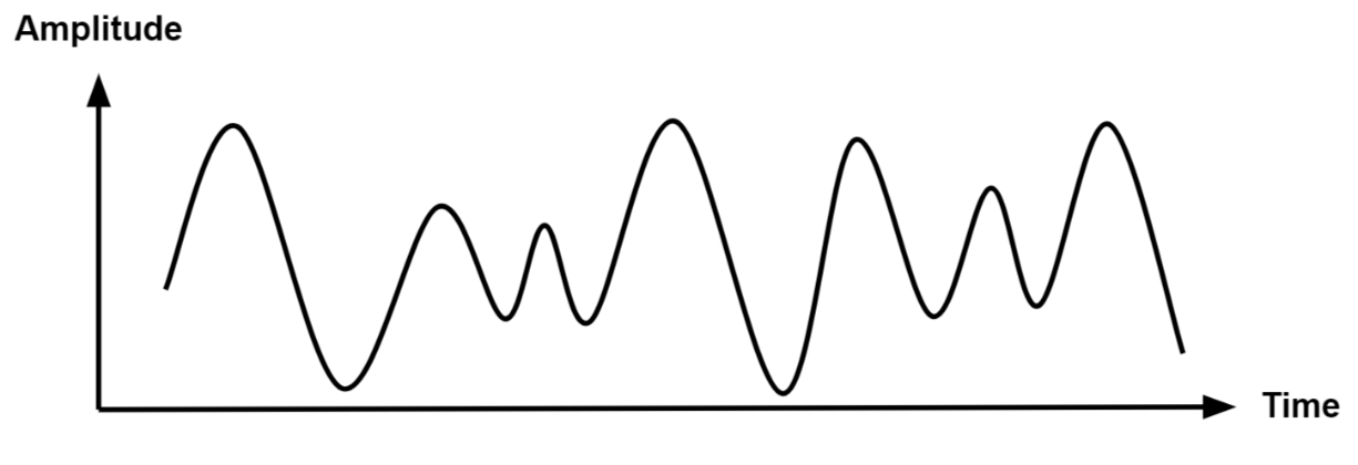
- An analog signal is time-varying and generally bound to a range (e.g. +12V to -12V), but there is an infinite number of values within that continuous range.
- An analog signal uses a given property of the medium to convey the signal’s information, such as electricity moving through a wire.
- In an electrical signal, the voltage, current, or frequency of the signal may be varied to represent the information.
- Analog signals are often calculated responses to changes in light, sound, temperature, position, pressure, or other physical phenomena.
- When plotted on a voltage vs. time graph, an analog signal should produce a smooth and continuous curve.
- There should not be any discrete value changes .
Digital Signal
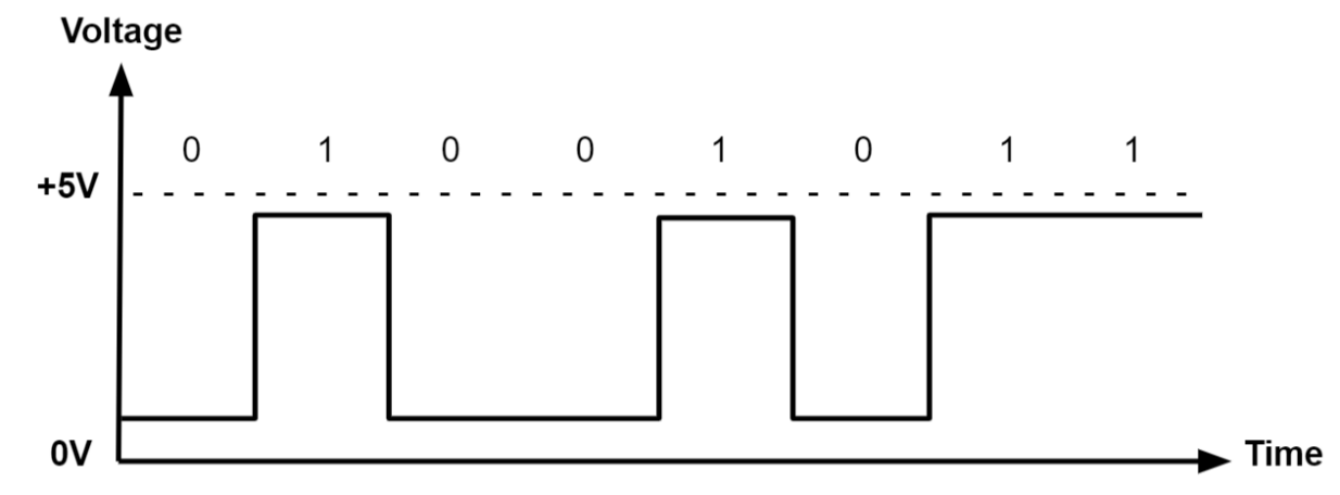
- A digital signal is a signal that represents data as a sequence of discrete values.
- A digital signal can only take on one value from a finite set of possible values at a given time.
- With digital signals, the physical quantity representing the information can be many things:
- Variable electric current or voltage
- Phase or polarization of an electromagnetic field
- Acoustic pressure
- The magnetization of a magnetic storage media
- Digital signals are used in all digital electronics, including computing equipment and data transmission devices. When plotted on a voltage vs. time graph, digital signals are one of two values, and are usually between 0V and VCC (usually 1.8V, 3.3V, or 5V) .
Difference: Analog & Digital Signal
| Parameter | Analog | Digital |
|---|---|---|
| Definition | Analog signals are used to communicate information in a continuous function of time. | A digital signal transmits data in a discrete function of time. |
| Signal values | Analog signals represent data and information using a continuous range of values. | Digital signals use discrete values 0 and 1. |
| Signal bandwidth | The bandwidth is low. | The bandwidth is high |
| Suitability | Analog signals are better suited for transmitting audio, video, and other data via communication channels. | The digital signals are appropriate for computer and digital electronic processes such as data storage and other things. |
| Effect of electronic noise | Analog signals are easily influenced by electrical noise. | Digital signals are more reliable and resistant to noise than Analog ones. |
| Accuracy | Because analog signals are more susceptible to noise, their accuracy is reduced. | As digital signals are noise-free, they have high accuracy. |
| Power consumption | Analog transmissions require more power to transmit data | Digital transmissions utilize less power than analog signals |
| Circuit components | Resistors, capacitors, inductors, and other components | Transistors, logic gates, ICs, etc. |
| Examples | Temperature, current, voltage, voice, pressure, and speed are all examples of analog signals. | Data storage in computer memory is one of the examples of digital signals. |
| Applications | Used in landline phones, thermometers, radios, and other devices. | Used in computers, keyboards, digital watches, and other electronic devices. |
Data Encoding
- Encoding is the process of converting the data or a given sequence of characters, symbols, alphabets etc., into a specified format, for the secured transmission of data.
- Decoding is the reverse process of encoding which is to extract the information from the converted format.
- Encoding is the process of using various patterns of voltage or current levels to represent 1s and 0s of the digital signals on the transmission link.
- The common types of line encoding are Unipolar, Polar, Bipolar, and Manchester.
Encoding Techniques
- Analog data to Analog signals: The modulation techniques such as Amplitude Modulation, Frequency Modulation and Phase Modulation of analog signals, fall under this category.
- Analog data to Digital signal: This process can be termed as digitization, which is done by Pulse Code Modulation (PCM). Hence, it is nothing but digital modulation. As we have already discussed, sampling and quantization are the important factors in this. Delta Modulation gives a better output than PCM.
- Digital data to Analog signal: The modulation techniques such as Amplitude Shift Keying (ASK), Frequency Shift Keying (FSK), Phase Shift Keying (PSK), etc., fall under this category. These will be discussed in subsequent chapters.
- Digital data to Digital signal: These are in this section. There are several ways to map digital data to digital signals.
Non Return to Zero (NRZ)
- NRZ Codes has 1 for High voltage level and 0 for Low voltage level.
- The main behavior of NRZ codes is that the voltage level remains constant during bit interval.
- The end or start of a bit will not be indicated and it will maintain the same voltage state, if the value of the previous bit and the value of the present bit are same.
- The following figure explains the concept of NRZ coding
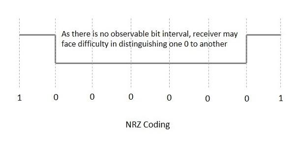
- If the above example is considered, as there is a long sequence of constant voltage level and the clock synchronization may be lost due to the absence of bit interval, it becomes difficult for the receiver to differentiate between 0 and 1
- There are two variations in NRZ namely:
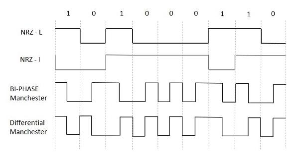
- NRZ - L (NRZ LEVEL):
- There is a change in the polarity of the signal, only when the incoming signal changes from 1 to 0 or from 0 to 1.
- It is the same as NRZ, however, the first bit of the input signal should have a change of polarity.
- NRZ - I (NRZ INVERTED):
- If a 1 occurs at the incoming signal, then there occurs a transition at the beginning of the bit interval.
- For a 0 at the incoming signal, there is no transition at the beginning of the bit interval.
- NRZ codes has a disadvantage that the synchronization of the transmitter clock with the receiver clock gets completely disturbed, when there is a string of 1s and 0s.
- Hence, a separate clock line needs to be provided.
Bi-phase Encoding
- The signal level is checked twice for every bit time, both initially and in the middle. Hence, the clock rate is double the data transfer rate and thus the modulation rate is also doubled.
- The clock is taken from the signal itself. The bandwidth required for this coding is greater.
- There are two types of Bi-phase Encoding:
- Bi-phase Manchester:
- In this type of coding, the transition is done at the middle of the bit-interval. The transition for the resultant pulse is from High to Low in the middle of the interval, for the input bit 1. While the transition is from Low to High for the input bit 0.
- Differential Manchester:
- In this type of coding, there always occurs a transition in the middle of the bit interval. If there occurs a transition at the beginning of the bit interval, then the input bit is 0. If no transition occurs at the beginning of the bit interval, then the input bit is 1.
Transmission Impairments
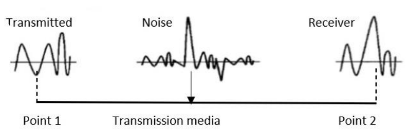
- Transmission impairment occurs when the received signal is different from the transmitted signal.
- As we know, a signal can be transmitted as Analog signal or it can be transmitted as a digital signal.
- In Analog signals due to transmission impairment the resulting received signal gets different amplitude or the shape.
- In the case of digitally transmitted signals at the receiver side we get changes in bits (0's or 1's).
- Causes of Transmission Impairments:
- Noise:
- Noise is the major factor for the transmission distortion as any unwanted signal gets added to the transmitted signal by which the resulting transmitted signal gets modified and at the receiver side it is difficult to remove the unwanted noise signal.
- These noises are various kinds like shot noise, impulse noise, thermal noise etc.
-
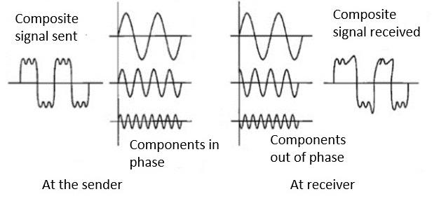
Distortion:
- This kind of distortion is mainly appearing in case of composite signals in which a composite signal has various frequency components in it and each frequency component has some time constraint which makes a complete signal.
- But while transmitting this composite signal, if a certain delay happens between the frequencies components, then there may be the chance that the frequency component will reach the receiver end with a different delay constraint from its original which leads to the change in shape of the signal.
- The delay happens due to environmental parameters or from the distance between transmitter and receiver etc.
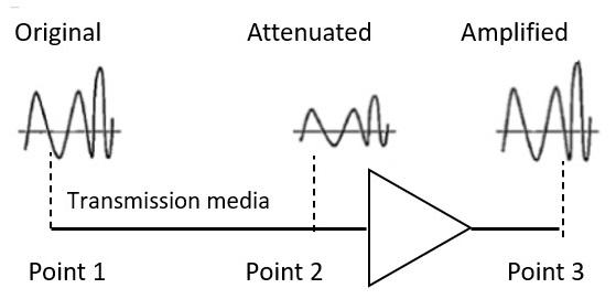
- Attenuation:
- Attenuation is generally decreased in signal strength, by which the received signal will be difficult to receive at the receiver end.
- This attenuation happens due to the majority factor by environment as environment imposes a lot of resistance and the signal strength decreases as it tries to overcome the resistance imposed.
Multiplexing methods
- Multiplexing is the sharing of a medium or bandwidth. It is the process in which multiple signals coming from multiple sources are combined and transmitted over a single communication/physical line.
Uses of Multiplexing
- Efficient Utilization of Resources: Multiplexing allows multiple signals to share the same communication channel, making the most of the available bandwidth. This is especially important in environments where bandwidth is limited.
- Telecommunications: In telephone networks, multiplexing enables the simultaneous transmission of multiple telephone calls over a single line, enhancing the capacity of the network.
- Internet and Data Networks: Multiplexing is used in internet communications to transmit data from multiple users over a single network line, improving the efficiency and speed of data transfer.
- Satellite Communications: Multiplexing helps in efficiently utilizing the available bandwidth on satellite transponders, allowing multiple signals to be transmitted and received simultaneously.
Types of Multiplexing
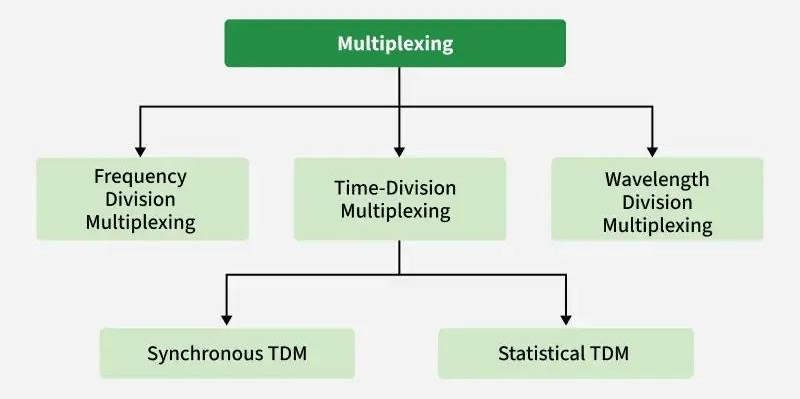
Frequency Division Multiplexing
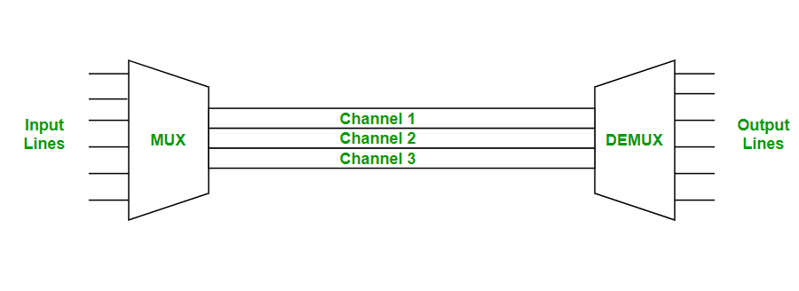
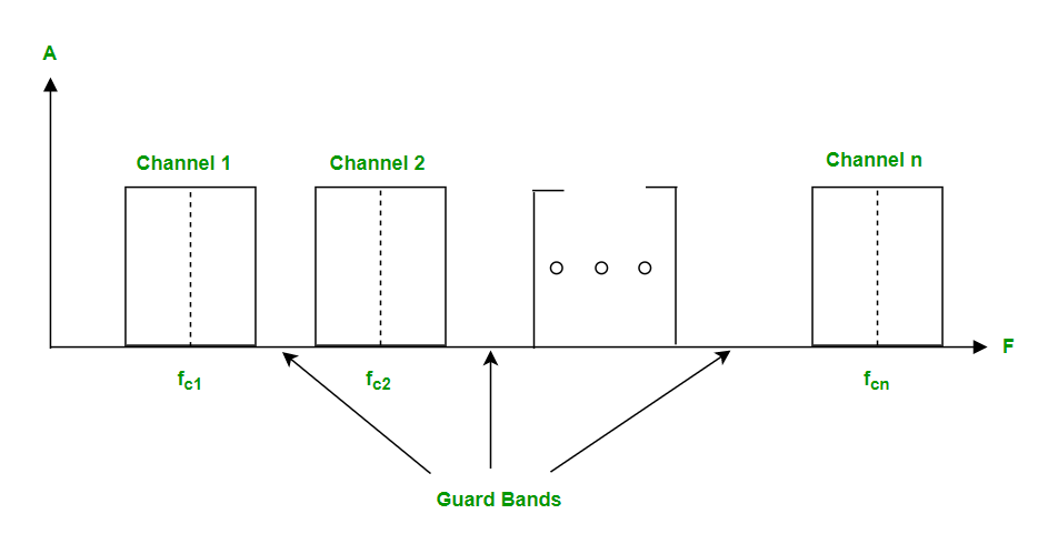
- Frequency division multiplexing is defined as a type of multiplexing where the bandwidth of a single physical medium is divided into a number of smaller, independent frequency channels.
- Frequency Division Multiplexing is used in radio and television transmission.
- In FDM, we can observe a lot of inter-channel cross-talk because in this type of multiplexing the bandwidth is divided into frequency channels.
- In order to prevent the inter-channel cross talk, unused strips of bandwidth must be placed between each channel.
- These unused strips between each channel are known as guard bands.
- Advantages of Frequency Division Multiplexing (FDM):
- Efficient Use of Bandwidth: FDM allows multiple signals to be transmitted over a single communication channel, which can lead to more efficient use of available bandwidth.
- No Time Synchronization Required: FDM does not require precise time synchronization between the transmitting and receiving devices, making it easier to implement
- Low Implementation Cost: FDM is a relatively simple technique that does not require sophisticated hardware or software, making it less expensive to implement.
- Disadvantages of Frequency Division Multiplexing (FDM):
- Limited Capacity: FDM is limited in terms of the number of signals that can be transmitted over a single communication channel, which can be a disadvantage in applications where a large number of signals need to be transmitted.
- Interference: FDM can be susceptible to interference from other signals transmitted on nearby frequencies, which can degrade the quality of the transmitted signal.
- Difficulty in Assigning Frequencies: FDM requires careful assignment of frequencies to different signals to avoid interference, which can be a complex and time-consuming process.
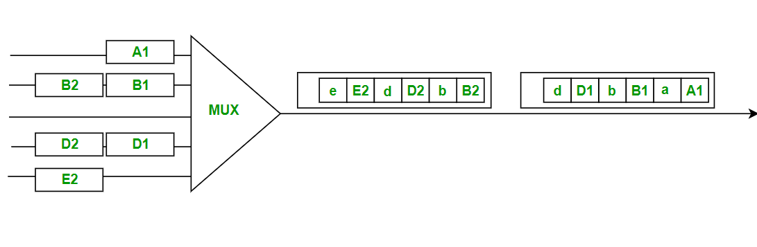
Time Division Multiplexing
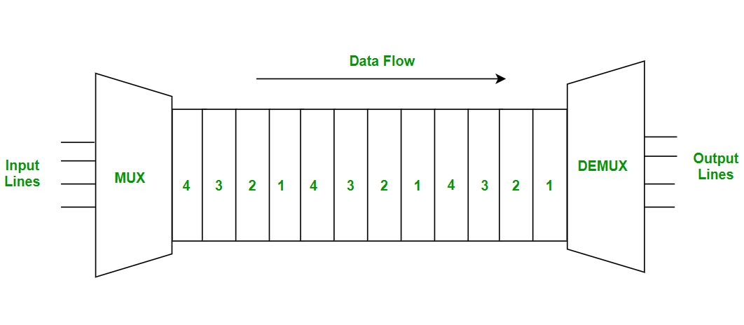
- Time-division multiplexing is multiplexing wherein FDM, instead of sharing a portion of the bandwidth in the form of channels, in TDM, time is shared.
- Each connection occupies a portion of time in the link. In Time Division Multiplexing, all signals operate with the same frequency (bandwidth) at different times.
- There are two types of Time Division Multiplexing:
- Synchronous TDM:
- Synchronous TDM is a type of Time Division Multiplexing where the input frame already has a slot in the output frame.
- Time slots are grouped into frames. One frame consists of one cycle of time slots.
- Synchronous TDM is not efficient because if the input frame has no data to send, a slot remains empty in the output frame.
- In this, we need to mention the synchronous bit at the beginning of each frame.
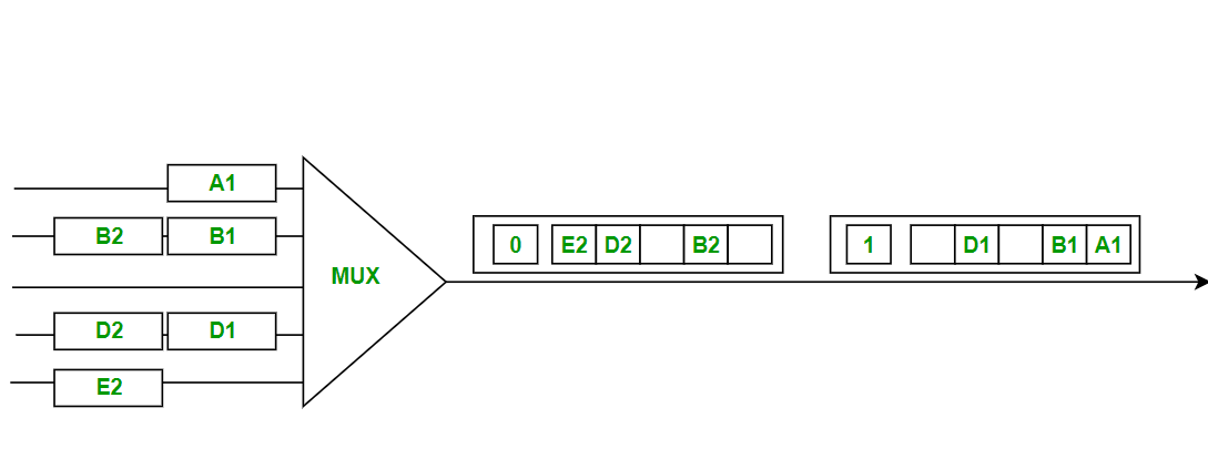
- Statistical TDM:
- Statistical TDM is a type of Time Division Multiplexing where the output frame collects data from the input frame till it is full not leaving an empty slot like in Synchronous TDM.
- In this, we need to include the address of each particular data in the slot that is being sent to the output frame.
- Statistical TDM is a more efficient type of time-division multiplexing as the channel capacity is fully utilized and improves the bandwidth efficiency.
- Advantages of Time Division Multiplexing (TDM):
- High Capacity: TDM can support a large number of signals over a single communication channel, making it ideal for applications where many signals need to be transmitted.
- Simple Implementation: TDM is a relatively simple technique that is easy to implement, making it a cost-effective solution for many applications.
- Precise Time Synchronization: TDM requires precise time synchronization between the transmitting and receiving devices, which can help ensure accurate transmission of signals
- Disadvantages of Time Division Multiplexing (TDM):
- Inefficient Use of Bandwidth: TDM may not make optimal use of available bandwidth, as time slots may be left unused if there are no signals to transmit during a particular time slot.
- High Implementation Cost: TDM requires sophisticated hardware or software to ensure precise time synchronization between the transmitting and receiving devices, making it more expensive to implement than FDM.
- Vulnerable to Timing Jitter: TDM can be vulnerable to timing jitter, which can occur when the timing of the transmitting and receiving devices drifts out of sync, leading to errors in the transmission of signals.
Wavelength Division Multiplexing
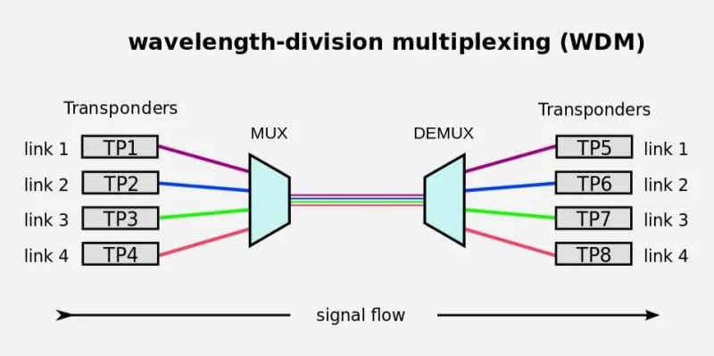
- Wavelength Division Multiplexing (WDM) is a multiplexing technology used to increase the capacity of optical fiber by transmitting multiple optical signals simultaneously over a single optical fiber, each with a different wavelength.
- Each signal is carried on a different wavelength of light, and the resulting signals are combined onto a single optical fiber for transmission.
- At the receiving end, the signals are separated by their wavelengths, demultiplexed and routed to their respective destinations.
- It is used in telecommunications, cable TV, ISPs, and data centers for high-speed, long-distance data transmission.
- WDM can be divided into two categories:
- Dense Wavelength Division Multiplexing (DWDM) is used to multiplex a large number of optical signals onto a single fiber, typically up to 80 channels with a spacing of 0.8 nm or less between the channels
- Coarse Wavelength Division Multiplexing (CWDM) is used for lower-capacity applications, typically up to 18 channels with a spacing of 20 nm between the channels.
- Advantages over Time Division Multiplexing (TDM):
- Higher data rates & capacity
- Lower power consumption
- Reduced equipment complexity
- Flexible & easily upgradable.
- Advantages of Multiplexing:
- Efficient Use of Bandwidth: You can send more than one signal over a single channel. This way, you can use the channel's capacity more efficiently.
- Increased Data Transmission: Multiplexing can significantly boost the amount of data that can be sent over a network simultaneously, enhancing overall transmission capacity.
- Scalability: Multiplexing allows networks to easily expand and accommodate more data streams without requiring significant changes to the existing infrastructure.
- Flexibility: Different types of multiplexing (TDM, FDM, WDM, CDM) can be used based on the specific needs and characteristics of the communication system, providing flexibility in network design.
- Disadvantages of Multiplexing:
- Synchronization Issues: Ensuring that multiple data streams remain properly synchronized can be challenging, leading to potential data loss or errors if not managed correctly.
- Latency: Combining multiple signals into one can introduce delays, as each data stream needs to be processed, synchronized, and demultiplexed at the receiving end.
- Signal Degradation: Over long distances, multiplexed signals can experience degradation and interference, requiring additional measures such as signal boosters or repeaters to maintain quality.
- Resource Management: Allocating and managing resources for multiplexing can be complicated, requiring careful planning and real-time adjustments to avoid congestion and ensure efficient operation.
Difference: FDM, TDM & WDM
| FDM | TDM | WDM |
|---|---|---|
| FDM is a multiplexing method used in analog systems that requires a guard band to prevent signals from overlapping. | TDM (Time Division Multiplexing) is a multiplexing technology and has low conflict, working with both digital and analog signals. | Wavelength division multiplexing (WDM) is often used for multiplexing numerous optical carrier signals into a single optical fiber channel. |
| FDM divides the bandwidth into smaller frequency ranges, and transmitters broadcast data concurrently across a shared channel inside each frequency range. | TDM provides each user a defined time slot to deliver signals across a shared channel. The user receives the complete bandwidth during that time frame. | WDM combines numerous light beams from different channels into a single light beam and delivers it over a fiber optic thread similar to FDM |
| FDM refers to Frequency Division Multiplexing. | TDM refers to Time Division Multiplexing. | WDM refers to Wave Length Multiplexing. |
| FDM is used in a communications network to send and receive input signals at maximum speed at all times. | This technology is used in GSM and also in SDH Transmission. | It is used in ultra-long- distance and high-capacity fiber systems. |
Switching Techniques
- Switching techniques in computer networks are used to connect devices and allow them to communicate with each other.
- Additionally, we can utilize switching techniques to transfer data from one device to another.
- Switching allows multiple devices to share the same communication channel simultaneously.
- As a result, it improves the efficiency of the network. Furthermore, switching also enables the network to route data to its intended destination.
- Additionally, it provides a mechanism for error checking and correction.
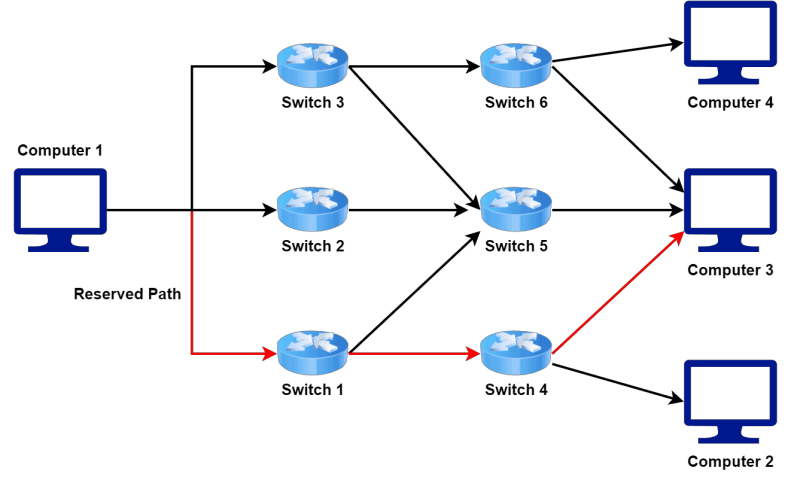
Circuit Switching
- We mainly use circuit switching in traditional telephone networks.
- When two devices want to communicate in a circuit-switched network, they establish a connection by setting up a dedicated path between them.
- This path is reserved exclusively for the duration of the communication. Hence, no other devices can use it during that specific time.
- Once we establish the connection, we can transfer data between devices over the dedicated path.
- This path typically comprises a series of interconnected switches or nodes that route the data to its destination.
- Let’s take a look at the general architecture of a network where we use circuit switching technique to transfer data from Computer 1 to Computer 3:
- Circuit switching isn’t commonly used in computer networks, as it isn’t very efficient for data transmission.
- We reserve the dedicated path for the entire duration of the communication.
- Therefore, we waste a significant amount of bandwidth during those times.
- Additionally, circuit switching is not well-suited for networks with high traffic volumes.
- However, we still use circuit switching in some specialized applications, such as in satellite communications, where the delay of packet switching can be prohibitive.
- Advantages:
- Circuit switching provides a dedicated communication path between two devices for the duration of the communication. Hence, we reserve the bandwidth for the entire conversation. This results in guaranteed bandwidth, which can be important for applications that require a constant data rate.
- As we reserve the dedicated communication for the entire conversation, there’s no packet loss. Finally, circuit switching provides predictable performance.
- Disadvantages:
- Some major disadvantages make it less suitable for modern computer networks. Let’s discuss some disadvantages of circuit switching.
- Circuit switching requires the dedicated communication path to be reserved for the entire duration of the communication. This results in an inefficient use of bandwidth, as the dedicated path isn’t being utilized during these times.
- Circuit switching isn’t well-suited for networks with high traffic volumes. This limits the scalability of circuit switching in large networks.
- Finally, it requires dedicated resources, such as switches or nodes, to establish the dedicated communication path. This can result in high costs for establishing and maintaining circuit-switched networks.
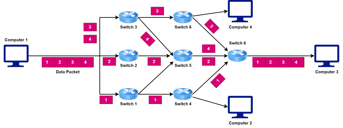
Packet Switching
- Packet switching is a method used to transmit data over a network.
- We divide data into small packets and transmit them over the network independently.
- Each packet contains the data and destination address information required to route the packet to its destination.
- In packet switching, each packet travels separately through the network and can take different paths to reach its destination.
- This approach allows for more efficient use of network resources because we can transmit multiple packets simultaneously over the same network.
- Let’s take a look at a network where we use packet switching technique to transfer data from Computer 1 to Computer 3:
- Packet switching is the basis for the Internet, which uses the Transmission Control Protocol/Internet Protocol (TCP/IP) suite of protocols for communication between devices.
- In this system, we transmit packets between devices, and routers along the way use the destination address information in each packet to route it to the next hop until it reaches its destination.
- Advantages:
- Packet switching offers several advantages over other data transmission methods, such as circuit switching. Let’s discuss some of the key benefits of packet switching.
- It allows multiple packets to be transmitted simultaneously over the network, making more efficient use of the available bandwidth.
- Packet switching is a robust and reliable method of data transmission. If one packet is lost or delayed, it doesn’t affect the transmission of other packets, as we route packets independently through the network.
- Packet switching is highly flexible. It can easily adapt to changing traffic patterns and network conditions.
- Disadvantages:
- While packet switching offers many advantages, there’re also some potential disadvantages.
- The process of breaking data into packets and adding header information to each packet can introduce additional overhead and latency into the transmission process. This can increase the time required for packets to reach their destination. Additionally, it can reduce the overall speed of data transmission.
- It can be vulnerable to security threats such as packet sniffing. This can compromise the privacy and security of data transmitted over the network. Furthermore, it can be complex to set up and manage, particularly in larger or more complex networks.
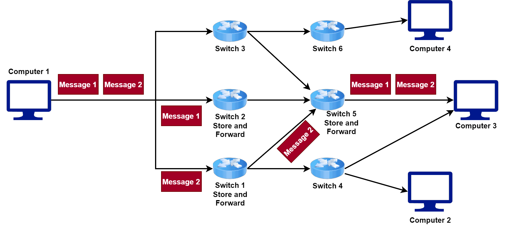
Message Switching
- Message switching is a method of data transmission that was popular in the early days of networking, before the development of packet switching.
- In message switching, we divide a message into fixed-length blocks or frames.
- Furthermore, we transmit each frame independently through the network.
- Additionally, each intermediate node stores the frames until the entire message is received. Finally, the nodes forward the entire message to its destination.
- Unlike packet switching, message switching is a store-and-forward method of data transmission.
- It means that each intermediate node stores the entire message until it can be forwarded to the next node.
- This can result in longer transmission times compared to packet switching.
- We can only transmit each message when an intermediate node receives all the parts of the message.
- Let’s take a look at a network where we use message switching technique to transfer data from Computer 1 to Computer 3:
- Advantages:
- While message switching is an older method of data transmission that has largely been replaced by packet switching, it does offer some advantages.
- Message switching is a highly reliable method of data transmission. Each intermediate node stores the entire message until it can be forwarded to the next node. This reduces the risk of data loss or corruption, as we store each message at intermediate nodes before forwarding them.
- It’s a simple method of data transmission that doesn’t require complex routing algorithms or network management techniques. This makes it easy to implement and manage, particularly in small or low- bandwidth networks.
- Message switching has a lower overhead compared to other methods of data transmission. This means that more bandwidth is available for data transmission.
- Disadvantages:
- It has several disadvantages compared to other methods.
- Message switching has a higher latency compared to other methods, such as packet switching. Additionally, it can be inefficient in terms of network resource utilization because each intermediate node must store the entire message until it can be forwarded.
- Finally, it requires more network resources for each message. This means that message-switching networks may be unable to support large numbers of devices or high-bandwidth applications.
Difference: Circuit , Message , & Packet Switching
| Parameter | Circuit Switching | Message Switching | Packet Switching |
|---|---|---|---|
| Connection Creation | Connection is created between the source and destination by establishing a dedicated path between source and destination | Links are created independently one by one between the nodes on the way | Links are created independently one by one between the nodes on the way |
| Queuing | No queue is formed | Queue is formed | Queue is formed |
| Message and Packets | There is one big entire data stream called a message | There is one big entire data stream called a message | The big message is divided into a small number of packets |
| Routing | One single dedicated path exists between the source and destination | Messages follow the independent route to reach a destination | Packets follow the independent path to hold the destination |
| Addressing and sequencing | Messages need not be addressed as there is one dedicated path | Messages are addressed as independent routes are established | Packets are addressed, and sequencing is done as all the packets follow the independent route |
| Propagation Delay | No | Yes | Yes |
| Transmission Capacity | Low | Max | Max |
| Sequence Order | Message arrives in Sequence | Message arrives in Sequence | Packets do not appear in sequence at the destination |
| Use Bandwidth | wastage | maximum extent | maximum extent |
Transmission Media Types
- Transmission media is the physical medium through which data is transmitted from one device to another within a network. These media can be wired or wireless.
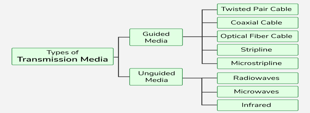
Guided Media
- We know that media is one of the responsibilities of the physical layer. Generally, the media is controlled by the physical layer and is used for the actual transmission of bits from the sender’s physical layer to the receiver’s physical layer.
- There are two types of media, guided media, and unguided media. We will discuss Guided Media in this tutorial.
- Guided media is a way of physically connecting devices to a network.
- Guided media is used when devices need to be connected to a network using cables. For example, connecting end devices to switches using cables is known as guided or wired networks.
- Guided media is also called wired media.
- Guided media uses cables between devices to transmit bits.
- Each device has a NIC (Network Interface Card), which connects to an intermediary device port using a cable on the network.
- Guided media uses Ethernet NIC to connect to the network while unguided media uses a wireless
Types of Guided Media
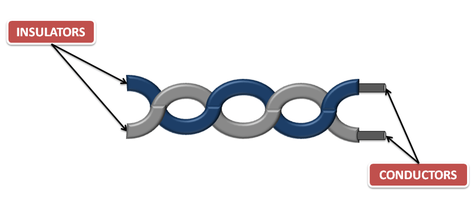
- Twisted Pair Cable:
- It is also known as copper cabling and is one of the most commonly used cablings in networks. Two insulated copper cables are twisted together in a helical form to prevent crosstalk and physical damage.
- It is commonly used in today’s networks to transmit bits from the sender’s physical layer to the receiver’s physical layer. It is made up of two insulated copper cables that are twisted together in a helical form to prevent crosstalk and physical damage.
- The purpose of twisting cables is to reduce crosstalk. When two cables are twisted, each one produces opposite waves that cancel out each other, which reduces the noise on a channel.
- In twisted pair cable, one copper cable is used to send the signal to the receiver and the other is used for earthing (grounding) purposes.
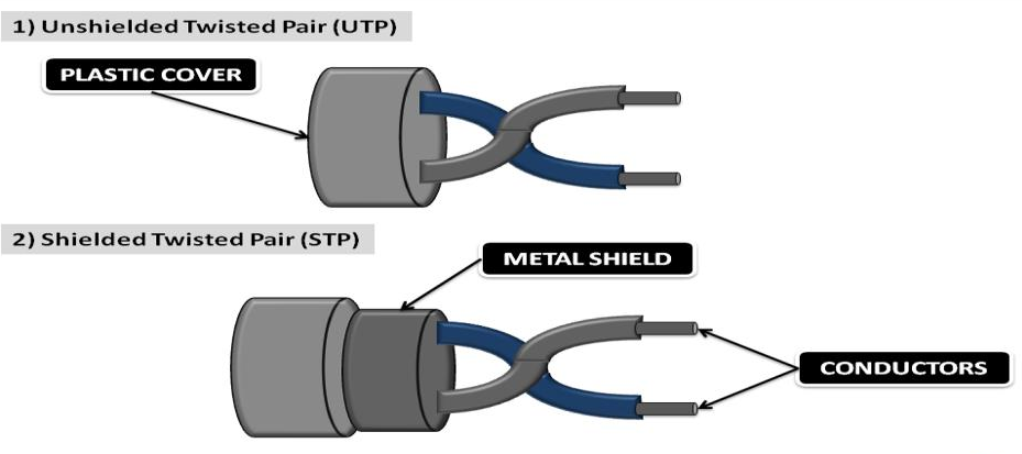
- Unshielded Twisted Pair Cable: UTP cables are commonly used to connect hosts to intermediary devices on a network using an RJ-45 connector. UTP cables consist of four different colored pairs of wires (orange, green, blue, and brown) that are shielded by a plastic sheath to prevent loss or damage to the signal.
- Straight through cable and crossover cable are the types of UTP cables.
- Straight-through cables are used to connect different types of devices on a network. For example, to connect end devices to switches or to connect switches to routers.
- Crossover cables are used to connect similar types of devices on a network. For example, to connect end device to end device or to connect router to router.
- Shielded Twisted Pair Cable: STP is more expensive than UTP and difficult to set up. The pair of the insulated conductor is shielded by metal.
- STP prevents crosstalk better than UTP. Both STP and UTP use RJ-45 connectors to connect devices.
- STP cable has 4 types of colored cables that are twisted together and wrapped with a braided shield, the braided shield is also protected by foil or metal to prevent physical damage.
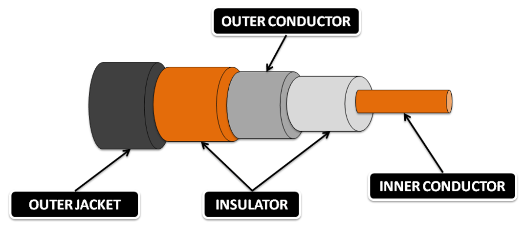
- Coaxial Cable:
- Coaxial cable has two conductors on the same axis that shield the cable.
- A copper cable surrounded by a copper conductor transmits electronic signals.
- The copper conductor is also shielded by an insulating material that acts as a second wire. And the whole cable is protected by the jacket.
- Coaxial cable has two conductors, the inner conductor and the outer conductor.
- The inner conductor of the coaxial cable transmits electronic signals, and the outer conductor is used to prevent noise on the channel.
- Bayonet Neill Concelman (BNC), N-type, and F-type are the types of connectors used in coaxial cable.
- BNC is the most commonly used connector of coaxial cable in Ethernet networks and cable TV.
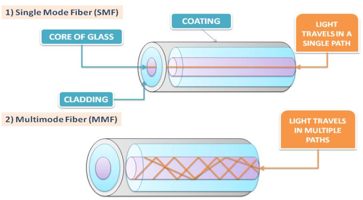
- Fibre Optics Cable:
- Fiber optic cables are made of glass and transmit bits in the form of light over the communication channel.
- Fiber optic cable is much more expensive than a twisted pair cable and a coaxial cable.
- Signals in fiber optic cable can travel very long distances because it provides high bandwidth.
- The signal loss in fiber optic cable is negligible. The fiber-optic cable transmits signals with very little attenuation.
- Single-mode fiber: It is very expensive and is used when the signal has to travel a very long distance. It sends the signal in light format. SMF is used in cable TV connections.
- Multi-mode fiber: The core of the MMF is larger than that of the SMF and transmits the signal in the form of a light pulse. It is used in LAN networks that have a range of about 500 meters
- SC (Subscriber Connector), ST (Straight Tip), Lucent Connector (LC), and Duplex Multimode LC (DMLC) are types of fiber optic connectors.
Difference: Twisted Pair, Coaxial & Fiber Optics Cable
| Parameter | Twisted Pair | Coaxial | Fiber Optics |
|---|---|---|---|
| Definition | Two insulated copper cables are twisted together in a helical form to prevent crosstalk and physical damage. | Coaxial cable has two conductors, the inner conductor and the outer conductor. Both conductors are shielded by insulators, and the whole cable is shielded by a jacket. | Fiber optic cables are made of glass that is very thin like human hair and transmits signals in the form of light over very long distances. |
| Bandwidth | Low | High | Very High |
| Cost | Cheap | Moderate | Expensive |
| Loss of Data | High | Moderate | Negligiable |
| Connectors | RJ-45 | BNC, N-Type, F-Type | SC, ST, LC, DMLC |
| Range | 100m | 200m-2Km | 100Km |
| Speed | 10 Mb/s - 100Gb/s | 10 Mb/s - 100Mb/s | 10 Mb/s - 200Gb/s |
| Uses | Connects end devices to Intermediary devices | Radio Frequency signals, Voice communication | Local Area Network, Long distance transmission |
Unguided Media
- The medium which transmits signals in the form of electromagnetic waves without using any physical conductor is known as unguided media.
- Unguided media is the second type of transmission media after guided media. It is used to connect devices to the network without using cables
- When unguided media is used to connect the end device to the network, the end device’s wireless NIC is used. Because, wired NIC is used in wired or guided media and wireless NIC is used in wireless or unguided media.
- Unguided media transmits signals that represent bits of data. Typically, unguided media represent bits of data using radio waves, microwaves, or infrared waves.
- IEEE and the telecommunications industry specify standards for wireless communications such as Wi- Fi, Bluetooth, and Wi-Max.
Types of Unguided Media
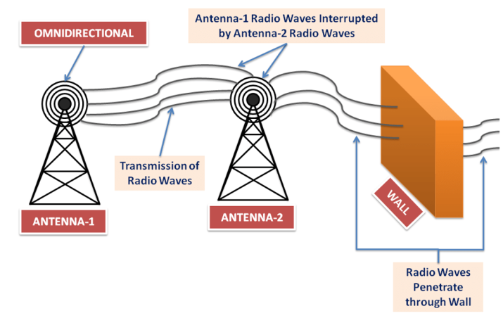
- Radio Waves Transmission:
- Unguided media transmit bits as electromagnetic waves having a range of 3 kHz to 1 GHz frequency, known as radio waves
- Radio waves are omnidirectional in nature, so when radio waves are transmitted through an antenna, they propagate in all directions.
- In simple words, sender and receiver antennas do not have to be aligned
- The main problem with radio waves here is that radio waves transmit signals in all directions, which can be interrupted by another antenna that uses the same frequency.
- Radio waves can travel long distances, so it is used in broadcasting. It can also penetrate through a wall because of its low frequency.
- The frequency of radio waves varies according to the wavelength, power, and purpose of transmission
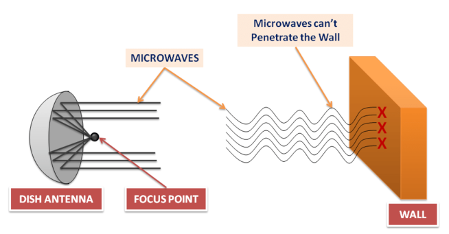
- Microwave Transmission:
- Unguided media transmit bits as electromagnetic waves having a frequency range of 1 GHz to 300 GHz, known as microwaves.
- Microwaves are unidirectional, which means that when antennas transmit signals, they transmit along a narrow-focused path.
- Due to the narrow path, the sender and receiver antenna have to be aligned.
- Microwaves are unidirectional, so the signal is transmitted without interfering with other antennas signals.
- When microwaves are of higher frequencies, they cannot penetrate walls like radio waves.
- For example, the sender sends a high-frequency microwave signal to the receiver, but the receiver is indoors, the signal will not be able to penetrate the wall, causing signal loss
- Infrared Waves Transmission:
- Unguided media transmit bits as electromagnetic waves having a frequency range of 300 GHz to 400 THz, known as infrared waves. Generally, infrared waves are used for short-distance communication.
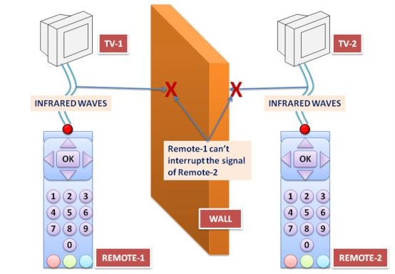
- Infrared waves block interference with other system waves.
- For example, when a user is communicating using infrared waves in a room, such as controlling a TV with a remote, it does not affect neighboring TVs.
- Infrared waves are not used for long-distance communication.
- Also, we cannot use infrared waves in the sun’s rays outside because the sun’s rays also contain infrared waves, which can interfere with other infrared waves and result in data loss.
- Infrared waves have very high bandwidth, such as 400 terahertz. Therefore infrared waves can transmit signals at a very high data rate.
- The Infrared Data Association (IRDA) has defined a data rate of 75 kbps, which can cover a distance of up to 8 meters. They have also defined another data rate which is 4 Mbps
Propagation in Unguided Media
- When a signal travels from sender to receiver, it can travel in different ways as follows
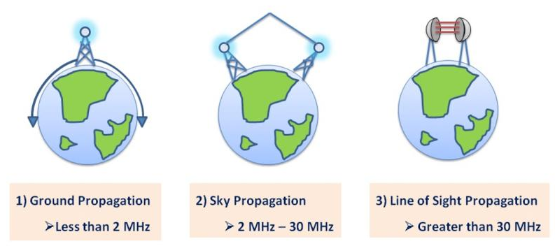
- Ground Propagation:
- It follows the curvature of the Earth, which means that radio waves travel very closely through the lowest part of the Earth’s atmosphere. It can measure the distance according to the signal strength.
- The higher the signal strength, the greater the distance the signal can travel.
- Ground Propagation is used in long-range radio navigation.
- Sky Propagation:
- In this propagation, the waves traveling upward into the ionosphere are reflected.
- The ionosphere is one of the layers of the atmosphere that consists of particles in the form of ions.
- In this transmission, the signals can travel long distances with minimum output power.
- Sky propagation is used in AM and FM radio, Very High-Frequency Television, and Citizen Band, etc.
- Line of sight Propagation:
- Signals of very high frequencies are transmitted from antenna to antenna in a straight line.
- Here the antennas used for transmission are facing each other and are directional.
- Line of sight propagation is used in cellular phones, satellite signals, and radars, etc.
Limitation of Unguided Media
- Unguided media limits effective coverage due to the materials used in buildings and local area networks.
- For example, if you are using microwaves for communication, then they cannot penetrate through the wall.
- Radio waves are interrupted by radio waves from other antennas because they are omnidirectional, increasing the likelihood of one radio wave colliding with other radio waves.
- Microwaves are unidirectional, but they cannot penetrate through a wall, which can cause an error in the signal.
- Wireless or unguided media do not have a physical shield, like guided media.
- Therefore, unauthorized access and loss of data increased, and the network administrator has to check media and network regularly.
- Wireless LAN uses a half-duplex mode for communication which means that one device can send or receive at a time, and wireless media is shared with all communication devices, which reduces the bandwidth of the network.
- This is because multiple users try to access the WLAN simultaneously
Difference: Radio, Micro, Infrared Waves
| Parameter | Radio Wave | Micro Wave | Infrared Wave |
|---|---|---|---|
| Definition | Unguided media transmit bits as electromagnetic waves having a range of 3 kHz to 1 GHz, known as microwaves | Unguided media transmit bits as electromagnetic waves having a range of 1 GHz to 300 GHz, known as microwaves. | Unguided media transmit bits as electromagnetic waves having a range of 300 GHz to 400 THz, known as microwaves. |
| Frequency | 3 kHz to 1 GHz | 1 GHz to 300 GHz | 300 GHz to 400 THz |
| Nature | Omnidirectional | Unidirectional | Short-range waves |
| Data Loss | Moderate | Low | Very Low |
| Advantage | Penetrate through the wall | One microwave does not interfere with another microwave | One infrared wave does not interfere with another infrared wave |
| Use | Used for long-distance transmission such as broadcasting | Used for unicast communication, such as military and radar | Used for short-distance communication such as controlling a TV with a remote |
Questions
- Explain Analog vs Digital Signals with diagrams and comparison.
- Explain the structure and working of twisted pair and coaxial cables.
- Why does NRZ face synchronization issues for long strings of 0s or 1s? How do Manchester and Differential Manchester solve this problem?
- Compare TDM, FDM, and WDM with respect to bandwidth, implementation, and applications.
- Draw and explain various switching techniques with real-time application areas.
- Encode the following bit stream using Manchester encoding: 10101100 Expected Rule: For bit '1': High to Low transition in the middle of the bit For bit '0': Low to High transition in the middle of the bit