CN-03 Data Link Control & MAC Protocols
On This Page
Data Link Control (DLC) Overview
- The Data Link Layer of the OSI model ensures reliable transmission of data frames between two nodes connected by a physical layer. Its main functions include:
- Framing (dividing bitstream into manageable units)
- Addressing (identifying sender & receiver)
- Error detection and correction
- Flow control
- Medium Access Control (MAC)
Error detection and correction techniques
- In computer networks, data integrity is essential.
- As data travels across various channels, it can be susceptible to errors due to noise, interference, or other anomalies.
- Error detection and correction techniques are vital in ensuring that the data received is accurate and reliable.
- Understanding these concepts is essential for designing robust communication systems and maintaining the integrity of data transmission.
What is Error Correction and Detection?
- Error correction refers to techniques used to identify and correct errors in data transmission or storage without requiring retransmission of the data.
- This process is crucial in ensuring data integrity, especially in environments where resending data is impractical or costly.
- This allows the receiver to detect and fix errors that may have occurred during transmission.
- Enabling error correction enhances the reliability of digital communication systems, ensuring that the information received is accurate and trustworthy
- On the other hand, error detection refers to the methods and techniques used to identify errors that may occur during the transmission or storage of data.
- The primary goal is to ensure that the data received matches what was originally sent.
- Error detection identifies the presence of errors, it plays an important role in maintaining data integrity in communication systems.
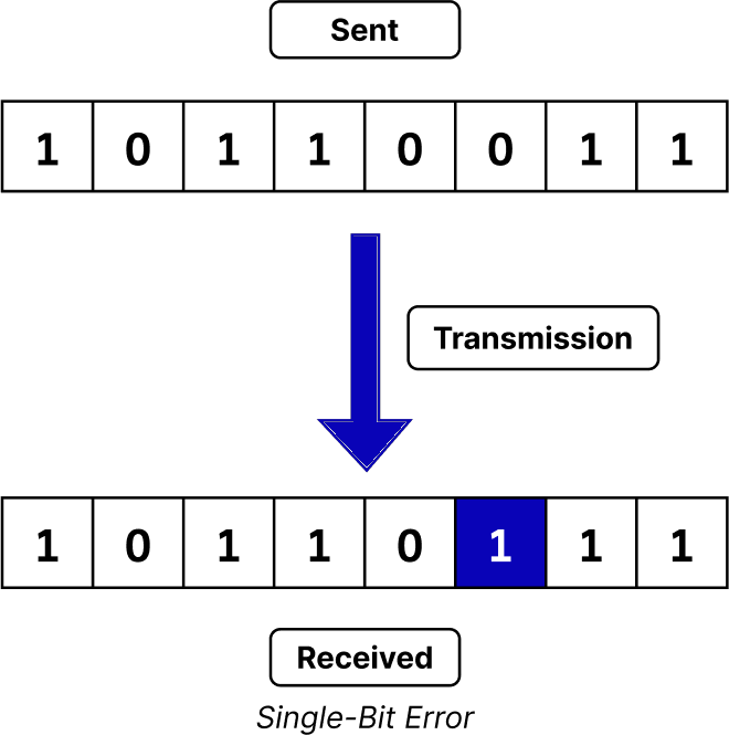
Types of Errors in Computer Networks
- Single-Bit Error: This type of error occurs when one bit of a transmitted data unit is altered, leading to corrupted data.
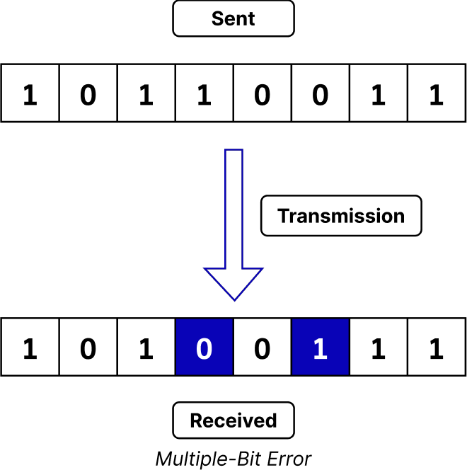
- Multiple-Bit Error: This type of error occurs when more than one bit is affected. While rarer than single-bit errors, they can occur in high-noise environments
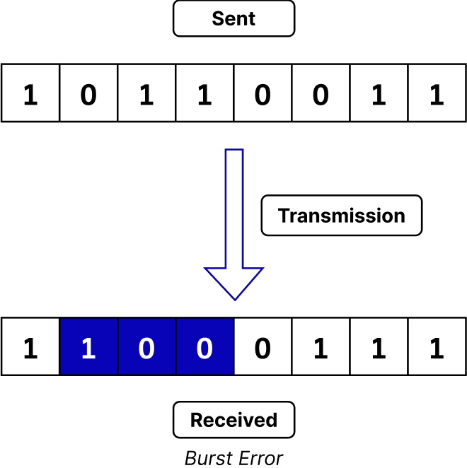
- Burst Error: This type of error occurs when a sequence of consecutive bits is flipped, resulting in several adjacent bits being incorrect.
Error Detection Techniques
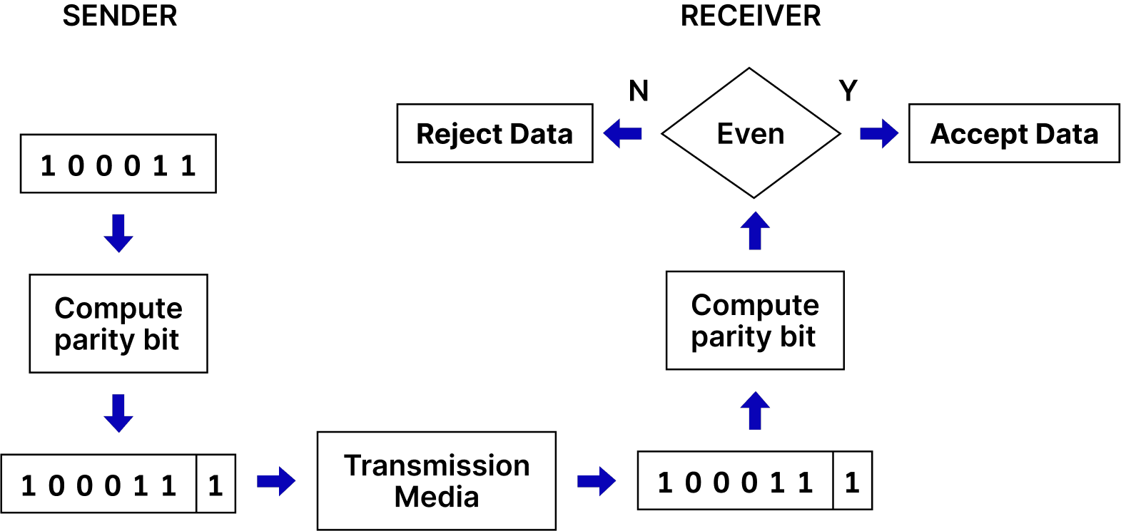
- Parity Bits: A simple method that adds a single bit to data to ensure the total number of 1s is even (even parity) or odd (odd parity).
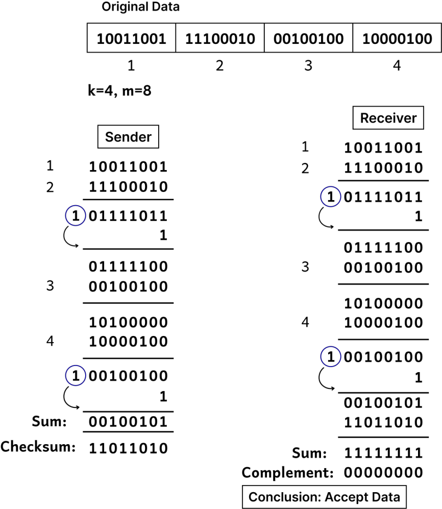
- Checksums: A mathematical sum of data values calculated before transmission and verified at the destination. If the checksum doesn't match, an error is detected.
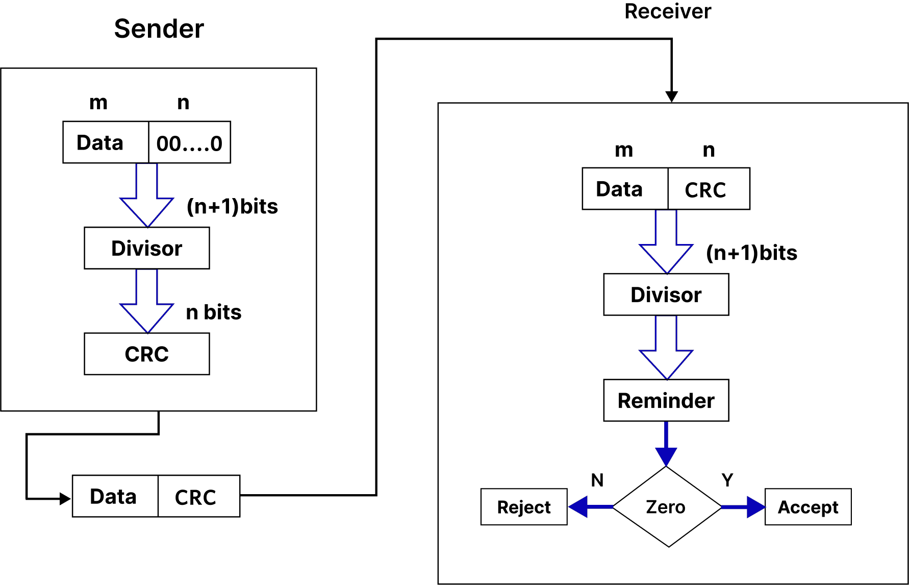
- Cyclic Redundancy Check (CRC): A more robust method that uses polynomial division to detect changes to raw data. CRCs are widely used in network communications and file storage
- Checksums with Hash Functions: Advanced checksum methods use cryptographic hash functions (like SHA-256) to ensure data integrity, particularly in secure communications.
Error Correction in Computer Networks
- Once the errors are detected in the network, the deviated bits sequence needs to be replaced with the right bit sequence so that the receiver can accept the data and process it. This method is called Error Correction. We can correct the errors in the Network in two different ways which are listed below:
- Forward Error Correction: In this Error Correction Scenario, the receiving end is responsible for correcting the network error. There is no need for retransmission of the data from the sender’s side.
- Backward Error Correction: the sender is responsible for retransmitting the data if errors are detected by the receiver. The receiver signals the sender to resend the corrupted data or the entire message to ensure accurate delivery.
- However, there is one of the most widely used Error Correction methods which is called ‘Hamming Code’ which was designed by R.W. Hamming. Let us have a quick look at it.
Hamming Code Error Correction
- n this method extra parity bits are appended to the message which are used by the receiver to correct the single bit error and multiple bit error.
- Consider the below example to understand this method in a better way.
- Suppose the sender wants to transmit the message whose bit representation is ‘1011001.’ In this message:
- Total number of bits (d) = 7
- Total of redundant bits (r) = 4 (This is because the message has four 1’s in it)
- Thus, total bits (d+r) = 7 + 4 = 11
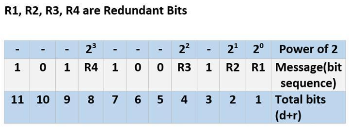
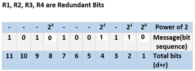
- Therefore, we have R1, R2, R3, and R4 as redundant bits which will be calculated according to the following rules:
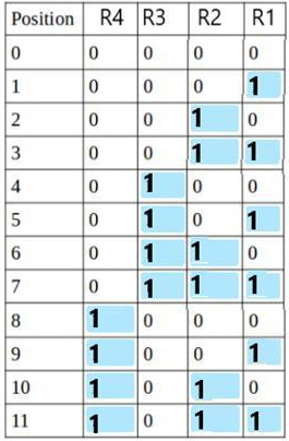
- R1 includes all the positions whose binary representation has 1 in their least significant bit. Thus, R1 covers positions 1, 3, 5, 7, 9, 11.
- R2 includes all the positions whose binary representation has 1 in the second position from the least significant bit. Thus, R2 covers positions 2,3,6,7,10,11.
- R3 includes all the positions whose binary representation has 1 in the third position from the least significant bit. Hence, R3 covers positions 4, 5, 6, 7.
- R4 includes all the positions whose binary representation has 1 in the fourth position from the least significant bit due to which R4 covers positions 8,9,10,11.
- Now, we calculate the value of R1, R2, R3 and R4 as follows:
- Since the total number of 1s in all the bit positions corresponding to R1 is an even number. R1 = 0.
- Since the total number of 1s in all the bit positions corresponding to R2 is an odd number, R2= 1.
- Since the total number of 1s in all the bit positions corresponding to R3 is an odd number, R3= 1.
- Since the total number of 1s in all the bit positions corresponding to R4 is even, R4 = 0.
- This message is transmitted at the receiver’s end. Suppose, bit 6 becomes corrupted and changes to 1. Then the message becomes ‘10101101110.’
- So, at the receiver’s end the number of 1’s in the respective bit positions of R1, R2, R3, and R4 is rechecked to correct the corrupted bit.
- This is done in the following steps: For all the parity bits we will check the
- For R1: bits 1, 3, 5, 7, 9, and 11 are checked. We can see that the number of 1’s in these bit positions is 4(even) so R1 = 0.
- For R2: bits 2,3,6,7,10,11 are checked. You can observe that the number of 1’s in these bit positions is 5(odd) so we get a R2 = 1.
- For R3: bits 4, 5, 6, and 7 are checked. We see that the number of 1’s in these bit positions is 3(odd). Hence, R3 = 1.
- For R8: bits 8,9,10,11 are observed. Here, the number of 1’s in these bit positions is 2 and that’s even so we get R4 = 0.
- If we observe the Redundant bits, they give the binary number 0110 whose decimal representation is 6.
- The error in bit 6 has been successfully identified and corrected.
- By rechecking the parity bits, we could detect that R4 was not matching its expected value, pointing us to the corrupted bit.
- The bit 6 should have been 1, and after correcting it, the message is now error-free.
Difference: Error Detection & Error Correction
| Error Detection | Error Correction |
|---|---|
| The purpose of error detection is to identify the presence of errors | The purpose of error correction is to correct the errors without retransmission |
| It is generally more efficient (lower overhead) | This can introduce higher overhead and complexity |
| It is much simpler to implement | It is more complex due to additional coding schemes |
| It has lower latency (only requires checking) | It contains higher latency (requires decoding and correction) |
| The error detection is used in networking (e.g., TCP, UDP) | The error correction is used in storage systems, error-prone environments (e.g., CDs, DVDs) |
| Examples of Error detection are Parity Check, CRC, Checksum | Examples of Error correction are Hamming Code, Reed-Solomon, Turbo Codes |
| This cannot fix errors, only detects them | It is limited to specific types and numbers of errors |
| It ensures data integrity during transmission | It ensures reliable data retrieval and storage |
Advantages of Error Detection
- Easier to implement with lower computational requirements.
- Faster processing since it only checks for errors rather than correcting them.
- Generally requires less additional data compared to error correction methods.
- Can identify errors quickly during data transmission.
Disadvantages of Error Detection
- Only detects errors but does not fix them, necessitating retransmission.
- May fail to detect certain types of errors, especially if multiple errors occur.
- Relies on the assumption that retransmission will resolve issues
Advantages of Error Correction
- Can correct errors to improve data integrity and reliability.
- Reduces the need for retransmission, which is beneficial in bandwidth-limited environments.
- Provides a higher level of error resilience, especially in noisy environments.
Disadvantages of Error Correction
- More complex to implement, requiring advanced algorithms and coding schemes.
- Involves additional bits for correction, which can increase the overall data size.
- Increased processing time due to the need for decoding and correcting errors.
- Can only correct a predetermined number of errors, beyond which data integrity may be compromised.
Flow control mechanisms
- Flow control is a technique that allows two stations working at different speeds to communicate with each other.
- It is a set of measures taken to regulate the amount of data that a sender sends so that a fast sender does not overwhelm a slow receiver.
- In data link layer, flow control restricts the number of frames the sender can send before it waits for an acknowledgment from the receiver.
- Flow control can be broadly classified into two categories:
- Feedback based Flow Control In these protocols, the sender sends frames after it has received acknowledgments from the user. This is used in the data link layer.
- Rate based Flow Control These protocols have built in mechanisms to restrict the rate of transmission of data without requiring acknowledgment from the receiver. This is used in the network layer and the transport layer
- Flow Control Techniques in Data Link Layer:
- Stop and Wait:
- The sender sends a frame and waits for acknowledgment.
- Once the receiver receives the frame, it sends an acknowledgment frame back to the sender.
- On receiving the acknowledgment frame, the sender understands that the receiver is ready to accept the next frame. So it sender the next frame in queue.
- Sliding Window:
- This protocol improves the efficiency of stop and wait protocol by allowing multiple frames to be transmitted before receiving an acknowledgment.
- Both the sender and the receiver have finite sized buffers called windows.
- The sender and the receiver agree upon the number of frames to be sent based upon the buffer size
- The sender sends multiple frames in a sequence, without waiting for acknowledgment.
- When its sending window is filled, it waits for acknowledgment.
- On receiving acknowledgment, it advances the window and transmits the next frames, according to the number of acknowledgments received.
- Stop and Wait:
MAC Addresses
- MAC address or media access control address is a unique identifier allotted to a network interface controller (NIC) of a device.
- It is used as a network address for data transmission within a network segment like Ethernet, Wi-Fi, and Bluetooth. MAC address is assigned to a network adapter at the time of manufacturing.
- It is hardwired or hard-coded in the network interface card (NIC).
- A MAC address comprises of six groups of two hexadecimal digits, separated
- A link-layer address is called a link address, called a physical address, and sometimes a MAC address.
- Since a link is controlled at the data-link layer, the addresses need to belong to the data-link layer.
- When a datagram passes from the network layer to the data-link layer,the datagram will be encapsulated in a frame and two data-link addresses are added to the frame header.
- These two addresses are changed every time the frame moves from one link to another.
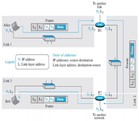
- Here we have three links and two routers. We have two hosts: Alice (source) and Bob (destination).
- For each host, we have shown two addresses, the IP addresses (N) and the link- layer addresses (L).
- We have three frames, one in each link.
- Each frame carries the same datagram with the same source and destination addresses (N1 and N8), but the link-layer addresses of the frame change from link to link.
- In link 1, the link-layer addresses are L1 and L2. In link 2, they are L4 and L5. In link 3, they are L7 and L8.
- Note that the IP addresses and the link-layer addresses are not in the same order.
- For IP addresses, the source address comes before the destination address; for link-layer addresses, the destination address comes before the source.
- Unicast Address: Each host or each interface of a router is assigned a unicast address. Unicasting means one to one communication. A frame with a unicast address destination is destined only for one entity in the link.
- Example: The unicast link-layer addresses in the most common LAN, Ethernet, are 48 bits (six bytes) that are presented as 12 hexadecimal digits separated by colons;
- For example, the following is a link-layer address of a computer: A3:34:45:11:92:F1
- Multicast Address: Some link-layer protocols define multicast addresses. Multicasting means one-to many communication.
- Example: The multicast link-layer addresses in the most common LAN, Ethernet, are 48 bits (six bytes) that are presented as 12 hexadecimal digits separated by colons. The second digit, needs to be an even number in hexadecimal.
- The following shows a multicast address: A2:34:45:11:92:F1
- Broadcast Address: Some link-layer protocols define a broadcast address. Broadcasting means one-to-all communication. A frame with a destination broadcast address is sent to all entities in the link
- Example: The broadcast link-layer addresses in the most common LAN, Ethernet, are 48 bits, all 1s, that are presented as 12 hexadecimal digits separated by colons.
- The following shows a broadcast address: FF:FF:FF:FF:FF:FF
Automatic Repeat Request (ARQ) protocols
- Automatic repeat request (ARQ), also known as automatic repeat query, is an error- control method for data transmission that uses acknowledgements (messages sent by the receiver indicating that it has correctly received a message) and timeouts (specified periods of time allowed to elapse before an acknowledgment is to be received) If the sender does not receive an acknowledgment before the timeout, it re-transmits the message until it receives an acknowledgment or exceeds a predefined number of retransmissions.
- ARQ is used to achieve reliable data transmission over an unreliable communication channel. ARQ is appropriate if the communication channel has varying or unknown capacity.
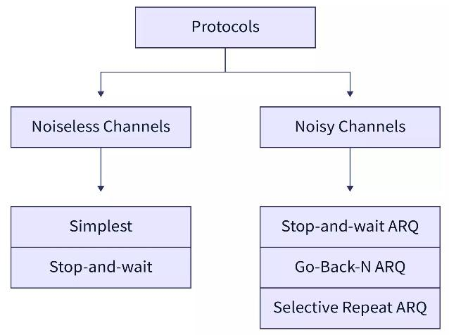
- Variations of ARQ protocols include Stop-and-wait ARQ, Go-Back-N ARQ, and Selective Repeat ARQ.
- All three protocols usually use some form of sliding window protocol to help the sender determine which (if any) packets need to be retransmitted.
- These protocols reside in the data link or transport layers (layers 2 and 4) of the OSI model.
- The data link is the second layer of the OSI model which is used for the transmission of the error-free frames from one node to the other node.
- If the two computer nodes are on the same network then the data link layer provides a connection between the two nodes.
- The main work of the data link layer is to convert the data into the form of frames.
- The flow control protocols involved in the data link layers are as follows
Stop and Wait ARQ
- The stop and wait ARQ protocol sends a data frame and then waits for an acknowledgment or ACK from the receiver.
- The ACK means that the receiver has successfully received the data frame.
- After the sender receives the ACK from the receiver, it sends the next data frame.
- So, there is a wait and then the next data frame is transmitted so the name came Stop and Wait ARQ protocol.
- In the stop and wait ARQ protocol, ARQ stands for Automatic Repeat Request.
- ARQ is an error-control strategy that ensures that a sequence of information is delivered in order and without any error or duplications despite transmission errors and losses.
- In the stop and wait ARQ, the sender also keeps a copy of the currently sending frame so that if the receiver does not receive the frame then it can retransmit it.
- In stop and wait ARQ, the sender sets a timer for each frame so whenever the timer is over and the sender has not received any acknowledgment for the frame, then the sender knows that the particular frame is either lost or damaged.
- So, the sender sends back the lost or damaged frame once the timer is out. So, we can see that the sender needs to wait for the timer to expire before retransmission
- There is no negative acknowledgment of the lost or damaged frames. So, there is no NACK (negative acknowledgment) in case of stop and wait ARQ.
- Let us learn the working of the stop and wait ARQ using an example in the next section.
Working Principle
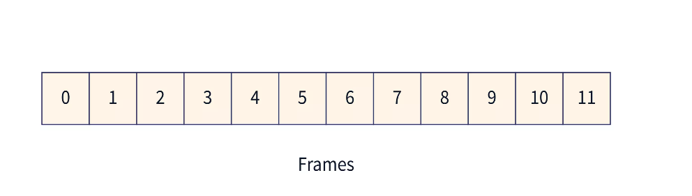
- Before learning about the working of the stop and wait ARQ, we should be familiar with the window size of the sender and receiver as the stop and wait ARQ is a type of sliding window protocol only.
- In the stop and wait ARQ, both the sender and the receiver have windows of the same size.
- The window on the sender’s side covers the sequence of data packets that are sent (or to be sent).
- On the other hand, the window on the receiver’s side covers the sequence of data packets that are received (or to be received).
- The size of the sender’s window is 1. The window size of the receiver is the same as that of the sender i.e. 1. The sender’s window size is represented using Ws and the receiver’s window size is represented using Wr.
- The overall working of the stop and wait ARQ is simple. Initially, the sender sends one frame as the window size is 1.
- The receiver on the other end receives the frame and sends the ACK for the correctly received frame.
- The sender waits for the ACK until the timer expires.
- If the sender does not receive the ACK within the timer limit, it re-transmits the frame for which the ACK has not been received.
- Now, let us take an example to visualize the working of stop and wait ARQ or how the data frame is transmitted using the stop and wait ARQ protocol.
- The image below shows the transmission of frames.
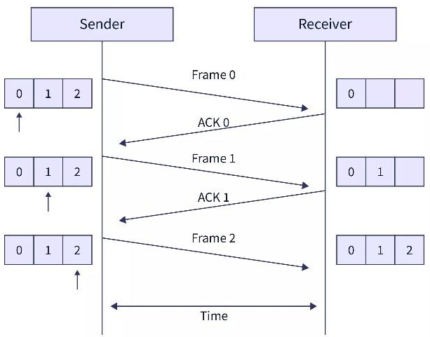
- The steps of data transmission can be:
- The sender sends frame 0.
- The sender waits for ACK from the receiver.
- The receiver receives the frame and sends back ACK 0.
- Again the sender sends the frame 1 and this process is continued till all the frames have been received by the receiver.
Problems
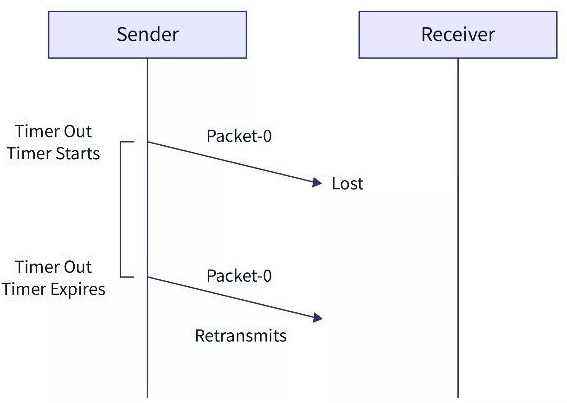
- Problem of Lost Data Packet:
- When the sender sends the data packet and the receiver does not receive the data packet, it means that the data is lost in between the transmission.
- So, to overcome this type of problem, the sender uses a timer. When the sender sends the data packet, it starts a timer.
- If the timer goes off before receiving the acknowledgment from the receiver, the sender retransmits the same data packet.
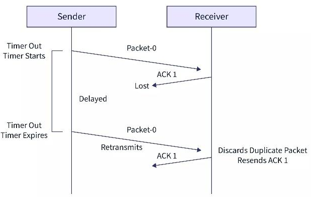
- Problem of Lost Acknowledgement:
- When the sender sends the data packet and the receiver receives the data packet but the acknowledgment from the receiver is not received. It means that the acknowledgment is lost in between the transmission.
- So, to overcome this type of problem, the sender uses sequence numbering.
- When the sender sends the data packet, it attaches a certain sequence number which helps the receiver identify the data packet.
- If the timer goes off before receiving the acknowledgment from the receiver, the sender retransmits the same data packet.
- But in this case, the receiver already has the data packet, so it discards the data and sends it back an acknowledgment.
- This tells the sender that the certain data packet is now received correctly.
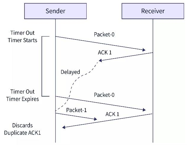
- Problem of Delayed Acknowledgement:
- When the sender sends the data packet and the receiver receives the data packet but the acknowledgment from the receiver is not received. It means that the acknowledgment is lost or delayed in between the transmission.
- So, to overcome this type of problem, the sender uses sequence numbering.
- When the sender sends the data packet, it attaches a certain sequence number which helps the receiver identify the data packet.
- If the timer goes off before receiving the acknowledgment from the receiver, the sender retransmits the same data packet.
- But in this case, the receiver already has the data packet, so it discards the data and sends it back the acknowledgment again.
- Now, if the sender has received the previously sent acknowledgment then the newer acknowledgment is discarded by the sender.
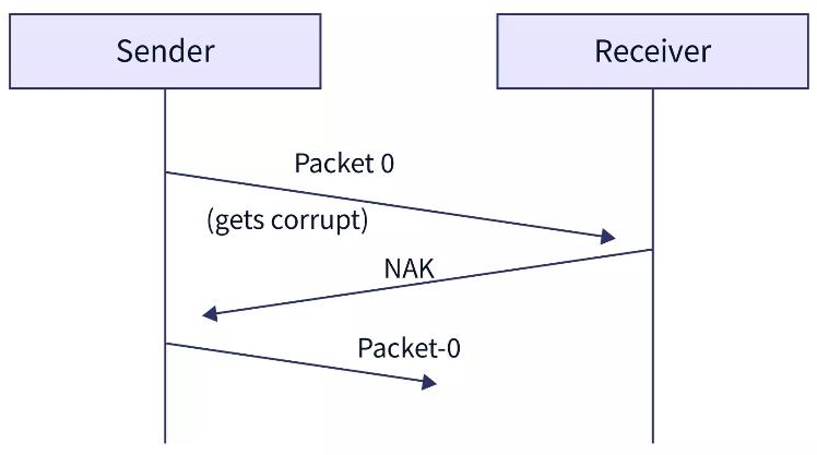
- Problem of Damaged Packet:
- When the sender sends the data packet and the receiver receives the data packet the received data packet is corrupted.
- So, to overcome this type of problem, the receiver uses negative acknowledgment (NACK). So, if the sender receives a negative acknowledgment then the sender retransmits the data packet.
Characteristics
- The stop and wait ARD is a sliding window protocol with a window size equal to 1.
- The stop and wait ARQ is an example of the Closed Loop OR connection-oriented.
- The sender sends the data frame with a sequence number.
- The sender also maintains a copy of the data frame that is being currently sent so that if the ACK is not received then the sender can re-transmit the frame.
- The sender can send only one frame at a time and the receiver can also receive only one frame at a time.
- The stop and wait ARQ is a connection-oriented protocol.
- In the stop and wait ARQ, the sender needs to maintain a time tracker.
Advantages
- The stop and wait ARQ can be used in both the data link layer and the transport layer.
- The stop and wait ARQ provides both error management and flow control management.
- The stop and wait ARQ works in half-duplex mode as at a time only the sender can send the message or the receiver can send the ACK.
- The stop and wait ARQ ensures that the information is received by the receiver in the order it was sent.
Limitations
- The data can be lost in between the transmission. So, in such a case, the sender waits for ACK and the receiver waits for the data frame for an infinite amount of time.
- The ACK from the receiver may get lost in the channel. So, the sender waits for ACK for an infinite amount of time.
- The window size of the sender and the receiver is only 1. So, only one frame can be sent at a time.
- As there is a timer concept, the sender must wait for a long duration before retransmission. Hence, the stop and wait ARQ is a slow protocol.
Go-Back-N ARQ Protocol
- Go Back N ARQ is a sliding window protocol which is used for flow control purposes.
- Multiple frames present in a single window are sent together from sender to receiver.
- Pipelining is allowed in the Go Back N ARQ protocol.
- Pipelining means sending a frame before receiving the acknowledgment for the previously sent frame.
- The sender window is a fixed-sized window that defines the number of frames that are transmitted from sender to receiver at once. The integer ‘N’ in the Go Back ‘N’ is the frame size.
- The Receiver window in the Go Back N ARQ protocol is always of size 1. This means that the receiver takes at most 1 frame at a single time.
Working Principle
- Data packets are divided into multiple frames. Each frame contains information about the destination address, the error control mechanism it follows, etc. These multiple frames are numbered so that they can be distinguished from each other.
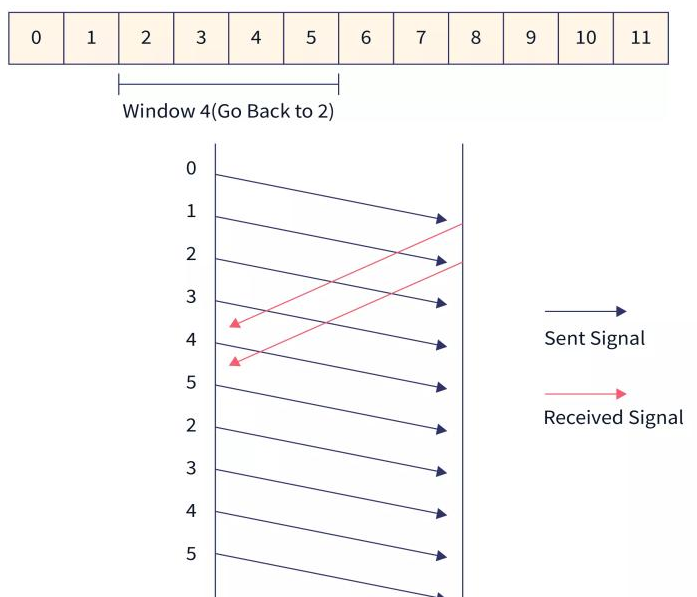
- The integer ‘N’ in Go Back ‘N’ ARQ tells us the size of the window i.e. the number of frames that are sent at once from sender to receiver. Suppose the window size ‘N’ is equal to 4. Then, 4 frames (frame 0, frame 1, frame 2, and frame 3) will be sent first from sender to receiver.
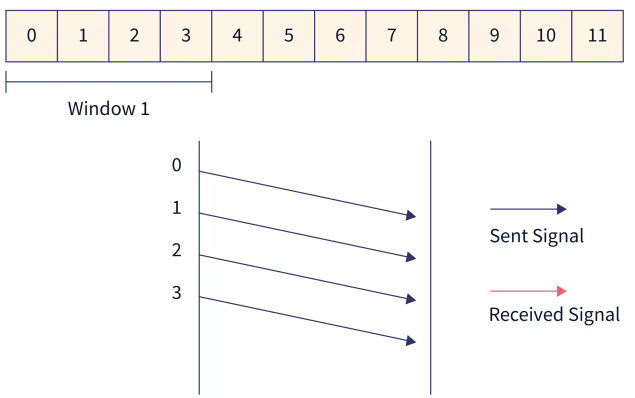
- The receiver sends the acknowledgment of frame 0. Then the sliding window moves by one and frame 4 is sent.
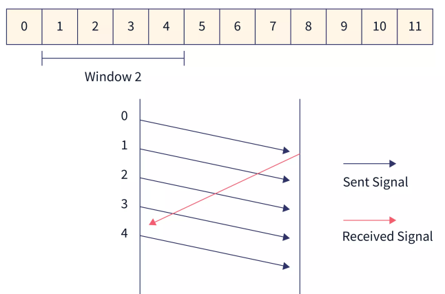
- The receiver sends the acknowledgment of frame 1. Then the sliding window moves by one and frame 3 is sent.
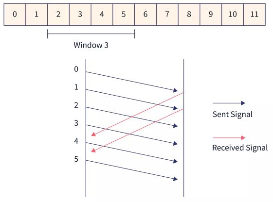
- The sender waits for the acknowledgment for a fixed amount of time. If the sender does not get the acknowledgment for a frame in time, it considers the frame to be corrupted. Then the sliding window moves to the start of the corrupted frame and all the frames in the window are retransmitted.
Characteristics
- The size of the sender window in Go Back N ARQ is equal to N.
- The size of the receiver window in Go Back N ARQ is equal to 1.
- When the acknowledgment for one frame is not received by the sender or the frames received by the receiver are out of order, then the whole window starting from the corrupted frame is retransmitted.
Advantages
- It can send multiple frames at once.
- Pipelining is present in the Go-Back-N ARQ i.e. a frame can be sent by the sender before receiving the acknowledgment of the previously sent frame. This results in a shorter waiting time for the frame.
- It handles corrupted as well as out-of-order frames which result in minimal frame loss.
Disadvantages
- If acknowledgment for a frame is not received, the whole window of frames is retransmitted instead of just the corrupted frame. This makes the Go Back N ARQ protocol inefficient.
- Retransmission of all the frames on detecting a corrupted frame increases channel congestion and also increases the bandwidth requirement.
- It is more time-consuming because while retransmitting the frames on detecting a corrupted frame, the error-free frames are also transmitted.
Here’s a summarized version of your notes in Markdown format. I’ve kept the wording close to the original while reducing repetition and organizing it with headings and bullet points.
Selective Repeat ARQ
-
Selective Repeat ARQ is a Sliding Window Protocol strategy.
-
Used where reliable in-order delivery of data packets is required.
-
Suitable for noisy channels or links, handling flow and error control between sender and receiver.
-
Only damaged or lost frames are retransmitted.
-
Uses ACK (Acknowledgment) for correct frames and NACK (Negative Acknowledgment) for lost/damaged frames.
-
Both ACK and NACK carry the sequence number of the frame.
-
What is Selective Repeat ARQ?
- Ensures reliable and ordered delivery of packets.
- Correctly received frames are buffered at the receiver.
- Damaged frames are selectively retransmitted.
- ARQ (Automatic Repeat Request): an error-control strategy to ensure delivery without errors or duplication.
-
Requirements for Error Control
-
Detect errors in transmission.
-
Use ACK and NACK to confirm delivery.
-
Enable sender to identify and retransmit lost or damaged frames.
-
Error Handling & Timer
- Sender sets a timer for each frame.
- If timer expires without acknowledgment, the frame is assumed lost/damaged and retransmitted.
- NACK improves efficiency by allowing immediate retransmission without waiting for timer expiry.
-
Receiver:
- Tracks sequence numbers.
- Buffers correct frames.
- Sends NACK for lost frames without discarding subsequent frames.
-
Sorting & Searching
- Receiver may get frames out of order → uses sequence numbers to sort frames.
- Sender must search for the specific lost frame when a NACK is received.
- These are minor drawbacks of the technique.
-
Sliding Window Protocol
- Sliding window allows sequential and reliable delivery of data frames.
- Sender can transmit multiple frames at a time.
- Other strategies:
- Stop & Wait ARQ (1-bit ARQ)
- Go-Back-N ARQ
Working Principle
- Both sender and receiver maintain windows of equal size.
- Sender’s window (Ws): frames sent or to be sent.
- Receiver’s window (Wr): frames received or expected.
- Window size = 2(m−1), where m = number of bits for sequence number.
- Process:
- Sender transmits frames within window.
- Receiver sends ACK for correct frames, NACK for damaged frames.
- Sender retransmits only the NACKed frames.
- Receiver sorts frames by sequence number for ordered delivery.
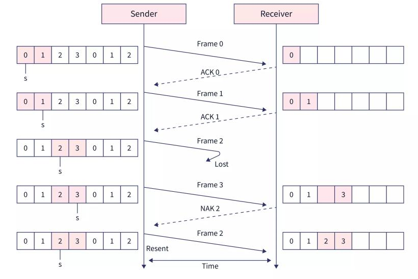
- The steps of data transmission can be:
- The sender sends frames 0 and 1.
- The receiver receives the frames and sends back ACK 0 and ACK 1.
- Again the sender sends the frames 2 and 3.
- The receiver only receives the frame 3. So it sends back NACK 2 which means that the 2nd frame is lost and needs to be re-transmitted.
- So, the sender sends back frame 2 and this process is continued till all the frames have been received by the receiver.
IEEE STANDARDS
- In 1985, the Computer Society of the IEEE started a project, called Project 802, to set standards to enable intercommunication among equipment from a variety of manufacturers.
- Project 802 does not seek to replace any part of the OSI or the Internet model.
- Instead, it is a way of specifying functions of the physical layer and the data link layer of major LAN protocols.
- The original Ethernet was created in 1976 at Xerox's Palo Alto Research Center (PARC).
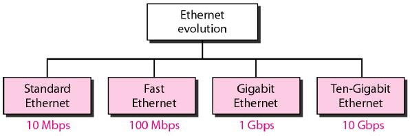
- Since then, it has gone through four generations:
- Standard Ethernet (10 Mbps),
- Fast Ethernet (100 Mbps),
- Gigabit Ethernet (1 Gbps),
- Ten-Gigabit Ethernet (10 Gbps)
Standard Ethernet(IEEE 802.3)
- Standard Ethernet also known as IEEE 802.3 was the LAN standard proposed by IEEE. Data rate for standard Ethernet is 10 Mbps.
- In Standard Ethernet, the MAC sublayer governs the operation of the access method. It also frames data received from the upper layer and passes them to the physical layer.
- The Ethernet frame contains seven fields: preamble, SFD, DA, SA, length or type of protocol data unit (PDU), upper-layer data, and the CRC.
- Ethernet does not provide any mechanism for acknowledging received frames, making it what is known as an unreliable medium. Acknowledgments must be implemented at the higher layers.
- The format of the MAC frame is shown in Figure.
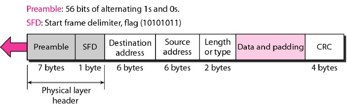
- Preamble:
- The first field of the 802.3 frame contains 7 bytes (56 bits) of alternating 0s and 1s that alerts the receiving system to the coming frame and enables it to synchronize its input timing.
- The pattern provides only an alert and a timing pulse. The 56-bit pattern allows the stations to miss some bits at the beginning of the frame.
- The preamble is actually added at the physical layer and is not (formally) part of the frame.
- Start frame delimiter (SFD):
- The second field (1 byte: 10101011) signals the beginning of the frame.
- The SFD warns the station or stations that this is the last chance for synchronization.
- The last 2 bits is 11 and alerts the receiver that the next field is the destination address.
- Destination address (DA):
- The DA field is 6 bytes and contains the physical address of the destination station or stations to receive the packet.
- Source address (SA):
- The SA field is also 6 bytes and contains the physical address of the sender of the packet.
- Length or type:
- This field is defined as a type field or length field. The original Ethernet used this field as the type field to define the upper-layer protocol using the MAC frame.
- The IEEE standard used it as the length field to define the number of bytes in the data field. Both uses are common today.
- Data:
- This field carries data encapsulated from the upper-layer protocols. It is a minimum of 46 and a maximum of 1500 bytes.
- CRC: The last field contains error detection information, in this case a CRC-32.
- Frame Length: Ethernet has imposed restrictions on both the minimum and maximum lengths of a frame, as shown in Figure.
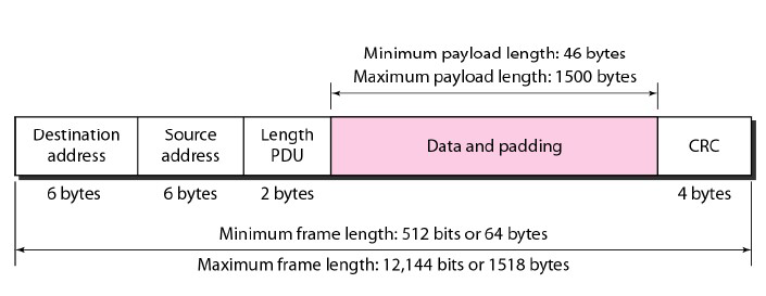
- The minimum length restriction is required for the correct operation of CSMA/CD as we will see shortly.
- An Ethernet frame needs to have a minimum length of 512 bits or 64 bytes. Part of this length is the header and the trailer.
- If we count 18 bytes of header and trailer (6 bytes of source address, 6 bytes of destination address, 2 bytes of length or type, and 4 bytes of CRC), then the minimum length of data from the upper layer is 64 - 18 = 46 bytes.
- If the upper-layer packet is less than 46 bytes, padding is added to make up the difference.
- The standard defines the maximum length of a frame (without preamble and SFD field) as 1518 bytes.
- If we subtract the 18 bytes of header and trailer, the maximum length of the payload is 1500 bytes.
- The maximum length restriction has two historical reasons. First, memory was very expensive when Ethernet was designed: a maximum length restriction helped to reduce the size of the buffer.
- Second, the maximum length restriction prevents one station from monopolizing the shared medium, blocking other stations that have data to send.
Categories of Standard Ethernet
-
10Base5: Thick Ethernet
- The first implementation is called 10Base5, thick Ethernet, or Thicknet. The nickname derives from the size of the cable, which is roughly the size of a garden hose and too stiff to bend with your hands.
- 10Base5 was the first Ethernet specification to use a bus topology with an external transceiver (transmitter/receiver) connected via a tap to a thick coaxial cable.
- The transceiver is responsible for transmitting, receiving, and detecting collisions.
- The transceiver is connected to the station via a transceiver cable that provides separate paths for sending and receiving.
- This means that collision can only happen in the coaxial cable.
- The maximum length of the coaxial cable must not exceed 500 m, otherwise, there is excessive degradation of the signal.
- If a length of more than 500 m is needed, up to five segments, each a maximum of 500-meter, can be connected using repeaters.
-
10Base2: Thin Ethernet
- The second implementation is called 10Base2, thin Ethernet, or Cheaper net.
- 10Base2 also uses a bus topology, but the cable is much thinner and more flexible.
- The cable can be bent to pass very close to the stations. In this case, the transceiver is normally part of the network interface card (NIC), which is installed inside the station.
- Note that the collision here occurs in the thin coaxial cable.
- This implementation is more cost effective than 10Base5 because thin coaxial cable is less expensive than thick coaxial and the tee connections are much cheaper than taps.
- Installation is simpler because the thin coaxial cable is very flexible.
- However, the length of each segment cannot exceed 185 m (close to 200 m) due to the high level of attenuation in thin coaxial cable.
-
10Base-T: Twisted-Pair Ethernet
- The third implementation is called 10Base-T or twisted-pair Ethernet. 10Base-T uses a physical star topology.
- The stations are connected to a hub via two pairs of twisted cable.
- Note that two pairs of twisted cable create two paths (one for sending and one for receiving) between the station and the hub.
- Any collision here happens in the hub.
- Compared to 10Base5 or 10Base2, we can see that the hub actually replaces the coaxial cable as far as a collision is concerned.
- The maximum length of the twisted cable here is defined as 100 m, to minimize the effect of attenuation in the twisted cable.
-
10Base-F: Fiber Ethernet
- Although there are several types of optical fiber 10-Mbps Ethernet, the most common is called 10Base-F.
- 10Base-F uses a star topology to connect stations to a hub.
- The stations are connected to the hub using two fiber-optic cables.
| Characteristics | 10Base5 | 10Base2 | 10Base-T | 10Base-F |
|---|---|---|---|---|
| Media | Thick Coaxial Cable | Thin Coaxial Cable | 2UTP | 2Fibre |
| Max Length | 500m | 185m | 100m | 2000m |
| Line encoding | Manchester | Manchester | Manchester | Manchester |
Fast Ethernet(IEEE 802.3u)
-
Fast Ethernet was designed to compete with LAN protocols such as FDDI or Fiber Channel (or Fibre Channel, as it is sometimes spelled).
-
IEEE created Fast Ethernet under the name 802.3u. Fast Ethernet is backward-compatible with Standard Ethernet, but it can transmit data 10 times faster at a rate of 100 Mbps.
-
The goals of Fast Ethernet can be summarized as follows:
- Upgrade the data rate to 100 Mbps.
- Make it compatible with Standard Ethernet.
- Keep the same 48-bit address.
- Keep the same frame format.
- Keep the same minimum and maximum frame lengths.
-
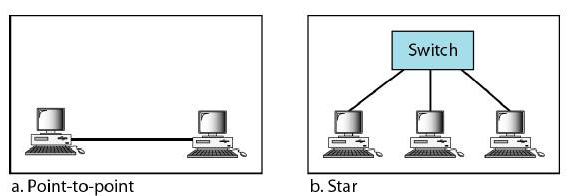
Topology:
- Fast Ethernet is designed to connect two or more stations together. If there are only two stations, they can be connected point-to-point.
- Three or more stations need to be connected in a star topology with a hub or a switch at the center
- Fast Ethernet implementation at the physical layer can be categorized as either two-wire or four-wire.
- The two-wire implementation can be either category 5 UTP (100Base-TX) or fiberoptic cable (100Base-FX).
- The four-wire implementation is designed only for category 3 UTP (100Base-T4)
| Characteristics | 100Base-TX | 100Base-FX | 100Base-T4 |
|---|---|---|---|
| Media | Cat5 UTP or STP | Fiber | Cat4 UTP |
| Number of wires | 2 | 2 | 4 |
| Medium Length | 100m | 100m | 100m |
| Line Encoding | MLT-3 | NRZ-I | 8B/6T |
Gigabit Ethernet (IEEE 802.3z)
-
The need for an even higher data rate resulted in the design of the Gigabit Ethernet protocol (1000 Mbps).
-
The IEEE committee calls the Standard 802.3z.
-
The goals of the Gigabit Ethernet design can be summarized as follows
- Upgrade the data rate to 1 Gbps.
- Make it compatible with Standard or Fast Ethernet.
- Use the same 48-bit address.
- Use the same frame format.
- Keep the same minimum and maximum frame lengths.
- To support autonegotiation as defined in Fast Ethernet.
-
Gigabit Ethernet has two distinctive approaches for medium access: half-duplex and fullduplex. Almost all implementations of Gigabit Ethernet follow the full-duplex approach
-
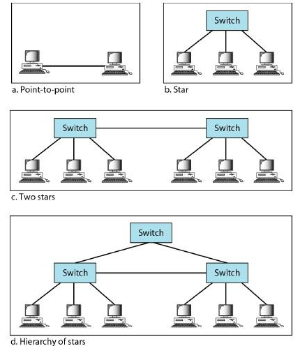
Topology:
- Gigabit Ethernet is designed to connect two or more stations. If there are only two stations, they can be connected point-to-point.
- Three or more stations need to be connected in a star topology with a hub or a switch at the center.
- Another possible configuration is to connect several star topologies or let a star topology be part of another
| Characteristics | 1000Base-SX | 1000Base-LX | 1000Base-CX | 1000Base-T |
|---|---|---|---|---|
| Media | Fiber short wave | Fiber long wave | STP | CAT5 UTP |
| Number of Wires | 2 | 2 | 2 | 4 |
| Max Length | 550m | 5000m | 25m | 100m |
| Line Encoding | NRZ | NRZ | NRZ | 4D-PAM5 |
Ten-Gigabit Ethernet(IEEE 802.3ae)
- The IEEE committee created Ten-Gigabit Ethernet and called it Standard 802.3ae.
- The goals of the Ten-Gigabit Ethernet design can be summarized as follows:
- Upgrade the data rate to 10 Gbps.
- Make it compatible with Standard, Fast, and Gigabit Ethernet.
- Use the same 48-bit address.
- Use the same frame format.
- Keep the same minimum and maximum frame lengths.
- Allow the interconnection of existing LANs into a metropolitan area network (MAN) or a wide area network (WAN).
- Make Ethernet compatible with technologies such as Frame Relay and ATM.
- Ten-Gigabit Ethernet operates only in full duplex mode which means there is no need for contention; CSMA/CD is not used in Ten-Gigabit Ethernet.
- Ten-Gigabit Ethernet is designed for using fiber-optic cable over long distances.
- Three implementations are the most common: 10GBase-S, 10GBase-L, and 10GBase-E.
| Characteristics | 10GBase-S | 10GBase-L | 10GBase-E |
|---|---|---|---|
| Media | Short-wave 850nm multinode | Long-wave 1310nm single node | Extended 1550nm single node |
| Max Length | 300m | 10km | 40km |
Wireless LAN Protocols
- Wireless LAN (WLAN) is a wireless distribution method for two or more devices to connect and communicate using radio waves instead of wires.
- The IEEE 802.11 standard, commonly known as Wi-Fi, outlines the architecture and defines the MAC and physical layer specifications for wireless LANs (WLANs).
- Wi-Fi uses high- frequency radio waves instead of cables for connecting the devices in LAN.
- Given the mobility of WLAN nodes, they can move unrestricted within the network coverage zone.
- The 802.11 structure is designed to accommodate mobile stations that participate actively in network decisions.
- Furthermore, it can seamlessly integrate with 2G, 3G, and 4G networks.
- The Wi-Fi standard represents a set of wireless LAN standards developed by the Working Group of IEEE LAN/MAN standards committee (IEEE 802).
- The term 802.11x is also used to denote the set of standards.
- Various specifications and amendments include 802.11a, 802.11b, 802.11e, 802.11g, 802.11n etc.
Important Terminologies of IEEE 802.11 Architecture
- Station: Stations (STA) comprise all devices and equipment that are connected to the wireless LAN. It can be of two types:
- Wireless Access Point (WAP): WAPs or simply access points (AP) are wireless routers that bridge connections for base stations.
- Client: Examples include computers, laptops, printers, and smartphones.
- Access Point: It is a device that can be classified as a station because of its functionalities and acts as a connection between wireless medium and distributed systems.
- Distribution System: A system used to interconnect a set of BSSs and integrated LANs to create an ESS.
- Frame: It is a MAC protocol data unit.
- SSID (Service Set Identifier): It’s the network name for a particular WLAN. All-access points and devices on a specific WLAN must use the same SSID to communicate.
- SDU: It is a data unit that acts as an input to each layer. These can be fragmented or aggregated to form a PDU.
- PDU: It is a data unit projected as an output to communicate with the corresponding layer at the other end. They contain a header specific to the layer.
- Network Interface Controller: It is also known as network interface card. It is a hardware component that connects devices to the network.
- Portal: Serves as a gateway to other networks
IEEE 802.11 Architecture and Services
- In the year 1990, IEEE 802.11 Committee formed a new working group, the IEEE 802.11 standard which defines protocols for Wireless Local Area Networks (WLANs).
- Just like how Ethernet provides services for wired media, IEEE 802.11 architecture is designed to provide features for wireless networks.
- An AP supports both wired and wireless connections. The 802.11 standard calls the upstream wired network the distribution system (DS).
- The AP bridges the wireless and wired L2 Ethernet frames, allowing traffic to flow from the wired to the wireless network and vice versa.
- Each wireless network has a unique SSID.
- The 802.11 architecture provides some basic services for WLANs whose implementation is supported by MAC layer
Basic Service Set
- The Basic Service Set configuration consists of a group of stations and relies on an Access Point (AP), which serves as a logical hub.
- Stations from different BSSs interact through the AP, which functions as a bridge, linking multiple WLAN cells or channels.
Operating Modes
- Infrastructure BSS: Communication between stations takes place through access points. The AP and its associated wireless clients define the coverage area and form the BSS.
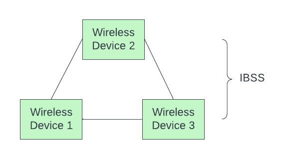
- Independent BSS: Supports mutual communication between wireless clients. An ad- hoc network is spontaneously created and does not support access to wired networks.
-
In the IBSS configuration, also referred to as independent configuration or ad-hoc network, no single node is required to act as a server.
-
The stations communicate directly with one another in a peer-to-peer basis. Generally, IBSS covers a limited area instead of a large network.
-
Typically covering a specific area, IBSS is used for specific, short-term purposes with a limited number of nodes.
-
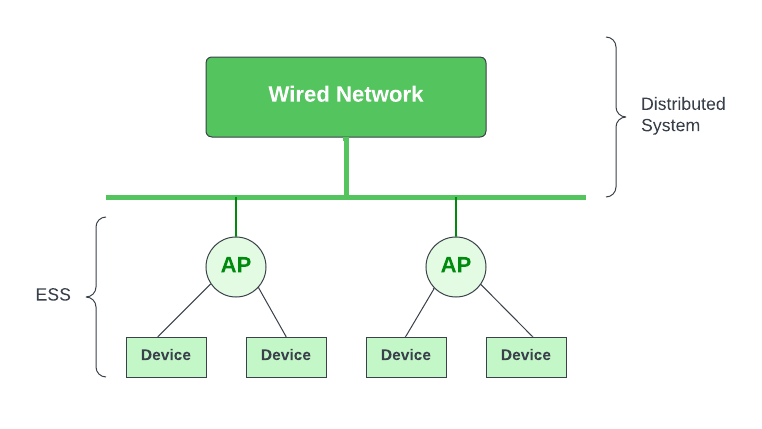
Extended Service Set:
- ESS connects multiple BSSs and consists of several BSS cells, which can be interlinked through wired or wireless backbones known as a distributed system.
- Multiple cells use the same channel to boost aggregate throughput to network.
- The equipment outside of the ESS, the ESS and all of its mobile stations comprise a single MAC layer network where all stations are virtually stationary.
- Thus, all stations within the ESS appear stationary from an outsider's perspective.
-
Other components include:
- Distribution System (DS): Links APs within the ESS.
- Portal: Serves as a gateway to other networks.
- Roaming: In an environment with multiple access points (like a large office building or campus), a device can move from the range of one AP to another and still maintain its connection. This is possible due to the underlying architecture of the IEEE 802.11 standard which allows for roaming between APs.
- Authentication and Association: Before a station can send or receive data frames on a WLAN, it needs to establish its identity with an AP. This process is called authentication. After authentication, the station then establishes a data link-layer connection with the AP through a process called association.
Frame Control
-
It is 2 bytes long and defines type of frame and control information. The types of fields present in FC are:
-
Version: Indicates the current protocol version.
-
Type: Determines the function of frame i.e. management(00), control(01) or data(10).
-
Subtype: Indicates subtype of frame like 0000 for association request, 1000 for beacon.
-
To DS: When set indicates that the destination frame is for DS(distribution system).
-
From DS: When set indicates frame coming from DS.
-
More frag (More fragments): When set to 1 means frame is followed by other fragments.
-
Retry: If the current frame is a re-transmission of an earlier frame, this bit is set to 1.
-
Power Mgmt (Power Management): It indicates the mode of a station after successful transmission of a frame. Set to '1' field indicates that the station goes into power-save mode. If the field is set to 0, the station stays active.
-
More data: It is used to indicate to the receiver that a sender has more data to send than the current frame.
-
WEP: It indicates that the standard security mechanism of 802.11 is applied.
-
Order: If this bit is set to 1 the received frames must be processed in strict order.
-
Duration ID: It contains the value indicating the period of time in which the medium is occupied (in µs).
-
Address 1 to 4: These fields contain standard IEEE 802 MAC addresses (48 bit each). The meaning of each address is defined by DS bits in the frame control field.
-
SC (Sequence Control): It consists of 2 sub-fields i.e. sequence number (12 bits) and fragment number (4 bits). Sequence number is used to filter duplicate frames.
-
Data: It is a variable length field which contains information specific to individual frames which is transferred transparently from a sender to the receiver.
-
CRC (Cyclic Redundancy Check): It contains 32 bit CRC error detection sequence to ensure error free frame.
-
Advantages of Wi-Fi:
- High data speed
- Easy installation
- Supports roaming
- Compatible with many devices
-
Disadvantages of Wi-Fi:
- Security risks (hacking)
- Limited range
- Interference from other devices
Bluetooth
- Bluetooth is a wireless technology that lets devices like phones, tablets, and headphones connect to each other and share information without needing cables.
- Bluetooth simply follows the principle of transmitting and receiving data using radio waves.
- It can be paired with the other device which has also Bluetooth but it should be within the estimated communication range to connect.
- When two devices start to share data, they form a network called piconet which can further accommodate more than five devices.
- Key Features of Bluetooth
- The transmission capacity of Bluetooth is 720 kbps.
- Bluetooth is a wireless technology.
- Bluetooth is a Low-cost and short-distance radio communications standard.
- Bluetooth is robust and flexible.
- The basic architecture unit of Bluetooth is a piconet.
Architecture of Bluetooth
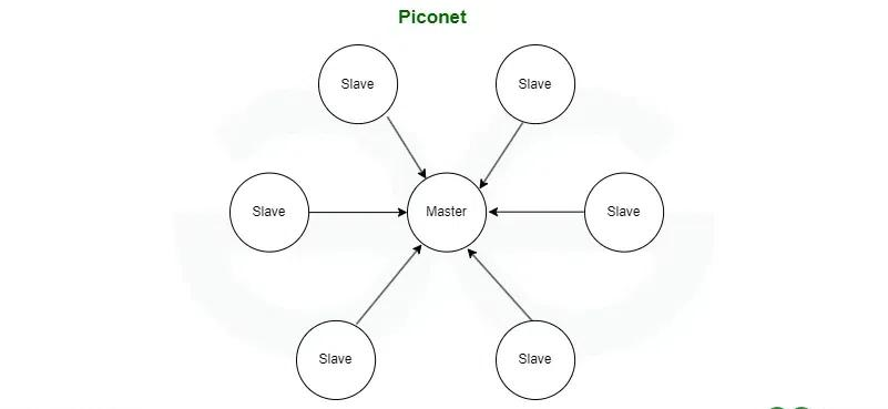
- Piconet:
- Piconet is a type of Bluetooth network that contains one primary node called the master node and seven active secondary nodes called slave nodes.
- Thus, we can say that there is a total of 8 active nodes which are present at a distance of 10 meters.
- The communication between the primary and secondary nodes can be one-to-one or one-to-many.
- Possible communication is only between the master and slave; Slave-slave communication is not possible.
- It also has 255 parked nodes, these are secondary nodes and cannot take participation in communication unless it gets converted to the active state.
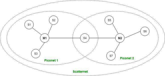
- Scatternet:
- It is formed by using various piconets.
- A slave that is present in one piconet can act as master or we can say primary in another piconet.
- This kind of node can receive a message from a master in one piconet and deliver the message to its slave in the other piconet where it is acting as a master.
- This type of node is referred to as a bridge node. A station cannot be mastered in two piconets.
Bluetooth Protocol Stack
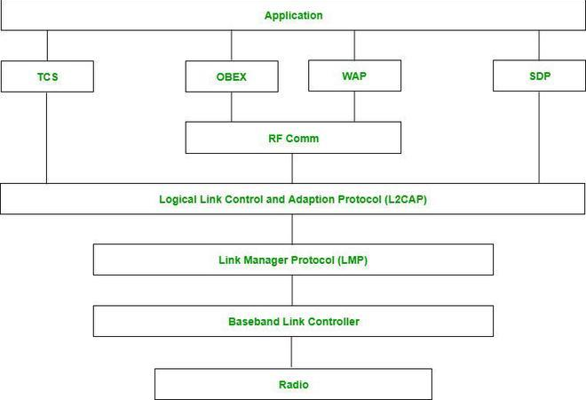
- Radio (RF) Layer:
- It specifies the details of the air interface, including frequency, the use of frequency hopping and transmit power.
- It performs modulation/demodulation of the data into RF signals. It defines the physical characteristics of Bluetooth transceivers.
- It defines two types of physical links: connection-less and connection-oriented.
- Baseband Link Layer:
- The baseband is the digital engine of a Bluetooth system and is equivalent to the MAC sublayer in LANs.
- It performs the connection establishment within a piconet, addressing, packet format, timing and power control.
- Link Manager Protocol Layer:
- It performs the management of the already established links which includes authentication and encryption processes.
- It is responsible for creating the links, monitoring their health, and terminating them gracefully upon command or failure.
- Logical Link Control and Adaption (L2CAP) Protocol Layer:
- It is also known as the heart of the Bluetooth protocol stack. It allows the communication between upper and lower layers of the Bluetooth protocol stack.
- It packages the data packets received from upper layers into the form expected by lower layers. It also performs segmentation and multiplexing.
- Service Discovery Protocol (SDP) Layer:
- It is short for Service Discovery Protocol. It allows discovering the services available on another Bluetooth-enabled device.
- RF Comm Layer:
- It is a cabal replacement protocol. It is short for Radio Frontend Component.
- It provides a serial interface with WAP and OBEX.
- It also provides emulation of serial ports over the logical link control and adaption protocol(L2CAP).
- The protocol is based on the ETSI standard TS 07.10.
- OBEX:
- It is short for Object Exchange. It is a communication protocol to exchange objects between 2 devices.
- WAP:
- It is short for Wireless Access Protocol. It is used for internet access.
- TCS:
- It is short for Telephony Control Protocol. It provides telephony service.
- The basic function of this layer is call control (setup & release) and group management for the gateway serving multiple devices.
- Application Layer:
- It enables the user to interact with the application.
Types of Bluetooth
- In-Car Headset: One can make calls from the car speaker system without the use of mobile phones.
- Stereo Headset: To listen to music in car or in music players at home.
- Webcam: One can link the camera with the help of Bluetooth with their laptop or phone.
- Bluetooth-Equipped Printer: The printer can be used when connected via Bluetooth with mobile phone or laptop.
- Bluetooth Global Positioning System (GPS): To use Global Positioning System (GPS) in cars, one can connect their phone with car system via Bluetooth to fetch the directions of the address.
Applications of Bluetooth
- It can be used in wireless headsets, wireless PANs, and LANs.
- It can connect a digital camera wireless to a mobile phone.
- It can transfer data in terms of videos, songs, photographs, or files from one cell phone to another cell phone or computer.
- It is used in the sectors of Medical healthcare, sports and fitness, Military.
Advantages
- It is a low-cost and easy-to-use device.
- It can also penetrate through walls.
- It creates an Ad-hoc connection immediately without any wires.
- It is used for voice and data transfer.
Disadvantages
- It can be hacked and hence, less secure.
- It has a slow data transfer rate of 3 Mbps.
- Bluetooth communication does not support routing.
Comparison: Wi-Fi & Bluetooth
| Parameter | Wi-Fi | Bluetooth |
|---|---|---|
| Standard | IEEE 802.11 | IEEE 802.15.1 |
| Range | up to 100m | up to 240m |
| Speed | up to 1Gbps | up to 2Mbps |
| Power Usage | High | Low |
| Application | Internet access | Device-to-device data transfer |
| Frequency | 2.4GHz / 5GHz | 2.4GHz |