CN Lab Manual
On This Page
Practical 01
Aim: Introduction to data Transmission in network.
Exercise:
- Write a program to convert character into binary and binary digits into character.
# Convert string to binary
string_input = input("Enter a string: ")
binary_output = ' '.join(format(ord(char), '08b') for char in string_input)
print("Binary value:", binary_output)
# Convert binary to string
binary_input = input("Enter binary (separate each 8-bit by space): ")
string_output = ''.join(chr(int(b, 2)) for b in binary_input.split())
print("String:", string_output)
Conclusion: This experiment shows how characters are converted to binary and back, which is the basic principle of data transmission in networks.
Practical 02
Aim: Study of networking devices
Exercise:
-
Define topology & list names of different topologies.
- A network topology is the arrangement of devices and connections in a network. It defines how devices communicate and impacts performance and reliability. Common topologies include: Bus, Star, Ring, Mesh, Tree, and Hybrid.
-
List out different kinds of addresses at layers with example.
| Form of data | Layer at address | Name of address | Example |
|---|---|---|---|
| Bits | Physical | Not Available | Not Available |
| Frames | Data Link | MAC Address | 00:1A:2B:3C:4D:5E |
| Packets | Network | IP Address | 127.0.0.1 |
| Segments | Transport | Port Number | 80, 5500, 443 |
| Messages | Application | URL | www.google.com |
-
What does RJ45 stand for?
- RJ45 stands for Registered Jack 45. It is a standard connector used for Ethernet cables to connect computers and networking devices.
-
Define mapping of:
- ARP: Address Resolution Protocol; maps IP address → MAC address
- RARP: Reverse Address Resolution Protocol; maps MAC address → IP address
-
Difference between HUB and SWITCH?
| Feature | Hub | Switch |
|---|---|---|
| Device Type | Networking device | Networking device |
| Layer | Operates at Layer 1 (Physical Layer) | Operates at Layer 2 (Data Link Layer) |
| Function | Broadcasts data to all ports | Sends data only to specific destination port |
| Data Transfer | Half-duplex (data flows one way at a time) | Full-duplex (simultaneous send & receive) |
| Intelligence | No filtering or learning capability | Yes—Learns MAC addresses and makes decisions |
| Speed & Efficiency | Slower, more collisions | Faster, fewer or no collisions |
| Security | Low (data sent to all devices) | Higher (data sent only to the right device) |
| Example Use Case | Small, outdated networks | Modern LANs, offices, enterprises |
| Cost | Cheaper | More expensive |
Conclusion: This experiment helps understand basic networking devices, their functions, and addressing, which are essential for network communication.
Practical 03
Aim: To study various networking commands
Exercise:
-
Why we are using
pingcommand?- The
pingcommand is used to test the connectivity between two network devices. It checks whether a device (like a computer or server) is reachable over the network and measures the round-trip time for messages sent.
- The
-
Explain
arpcommand.- The
arp(Address Resolution Protocol) command is used to view and manage the ARP table on a device. It shows the mapping between IP addresses and MAC addresses, helping in resolving network layer addresses to link layer addresses.
- The
Conclusion: This experiment helps understand basic networking commands, their purpose, and how they assist in network troubleshooting and device communication.
Practical 04
Aim: Introduction/installation of CISCO packet tracer, understanding of point to point network with net map, create network topology with HUB/Switch and simulate it.
Transfer PDU and view scenario graphically.
1. Which protocol is used to test scenario while simulation?
- The protocol used is ICMP (Internet Control Message Protocol). It is mainly used by the ping command to check connectivity between devices in a network. When one PC sends an ICMP Echo Request, the other PC replies with an ICMP Echo Reply. If the reply is received successfully, it confirms that the network connection is working properly.
Exercise: Create and Simulate a Network Topology Using a Hub
Objective: Create a network topology with more than two devices connected using a hub. Simulate the topology using any network simulation software (e.g., Cisco Packet Tracer). Take a screenshot of your network setup, print it, and paste the printed screenshot as required.
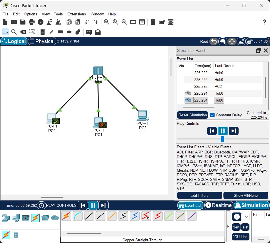
Steps:
- Open Packet Tracer → Add 1 Hub & 3 PCs.
- Connect each PC to Hub using Copper Straight cable.
- Assign IP addresses:
- Right-click PC → Desktop → IP Configuration
- Set IPs: 10.0.0.2, 10.0.0.3, 10.0.0.4 (Subnet: 255.0.0.0).
- Test connectivity using ping command in Command Prompt.
- Transfer PDU → View results in Simulation.
Exercise: Create and Simulate a Network Topology Using a Switch
Objective: Create a network topology with more than two devices connected using a switch. Simulate the topology using any network simulation software (e.g., Cisco Packet Tracer). Take a screenshot of your network setup, print it, and paste the printed screenshot as required.
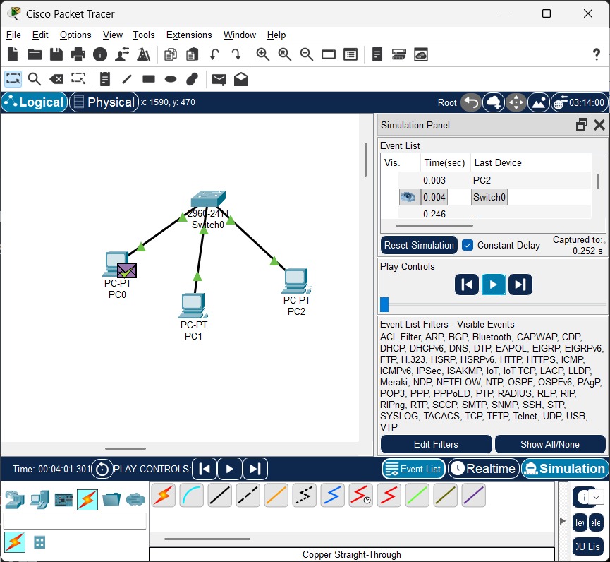
Steps:
- Open Packet Tracer → Add 1 Switch & 3 PCs.
- Connect each PC to Switch using Copper Straight cable.
- Assign IP addresses:
- Right-click PC → Desktop → IP Configuration
- Set IPs: 192.168.1.2, 192.168.1.3, 192.168.1.4 (Subnet: 255.255.255.0).
- Test connectivity using ping command in Command Prompt.
- Transfer PDU → View results in Simulation.
Conclusion: In this practical, we created and simulated point-to-point, hub, and switch-based networks using Cisco Packet Tracer. IP addresses were assigned, and connectivity was successfully tested using the ping (ICMP) protocol.
Practical 05
Aim: Introduction to different types of wired transmission media
Exercise:
- Compare different types of light sources used in optical fiber.
| Feature | LED (Light Emitting Diode) | Laser Diode |
|---|---|---|
| Wavelength | Broad range (850–1300 nm), may cause signal dispersion over long distances | Narrow range (1300–1550 nm), less signal loss, ideal for long distances |
| Power Output | Low, suitable for short-distance communication like LANs | High, suitable for long-distance communication like WANs or internet backbones |
| Bandwidth | Limited bandwidth, restricts data transmission speed | High bandwidth, supports high-speed data transmission |
| Cost & Size | Cheaper, easy to manufacture, larger in size | Expensive, compact, requires precise alignment |
| Applications & Efficiency | Used in short-distance, low-speed communication; moderate efficiency | Used in long-distance, high-speed networks; high efficiency and minimal loss |
-
List out different types of wired media used in computer lab with their specifications.
-
Twisted Pair Cable (UTP/STP): Consists of pairs of insulated copper wires twisted together to reduce interference. Used in LANs. Categories include Cat5e and Cat6. Maximum distance ~100m, speed up to 1 Gbps (Cat5e) and 10 Gbps (Cat6).
-
Coaxial Cable: Single copper conductor with insulating layer, metal shield, and outer insulation. Used in older networks and cable TV. Moderate bandwidth, distance up to 500m, resistant to interference.
-
Fiber Optic Cable: Uses glass or plastic fibers to transmit data as light pulses. Supports very high speeds (up to 100 Gbps), long distances (several kilometers), and is immune to electromagnetic interference. Used in backbone networks.
-
Shielded Twisted Pair (STP): Twisted pair cable with extra shielding to protect against electromagnetic interference. Slightly more expensive than UTP, used in industrial environments.
-
Ethernet Cable (Cat5e / Cat6 / Cat6a): Standard cable for LAN connections, supports high-speed data transmission. Cat5e: up to 1 Gbps, Cat6: up to 10 Gbps for short distances. Easy to install and widely used in labs.
-
-
Give difference between following:
(A) Twisted Pair Cable and Coaxial Cable
| Feature | Twisted Pair Cable | Coaxial Cable |
|---|---|---|
| Structure | Pairs of insulated copper wires twisted together | Central conductor with insulating layer and metallic shield |
| Interference | Reduces interference through twisting | Reduces interference using shielding |
| Cost | Generally cheaper | More expensive |
| Flexibility | More flexible and easier to install | Less flexible, especially thicker types |
| Application | Ethernet LANs, telephone lines | Cable TV, broadband, older LANs |
(B) Twisted Pair Cable and Fiber Optic Cable
| Feature | Twisted Pair Cable | Fiber Optic Cable |
|---|---|---|
| Medium | Copper wires | Glass or plastic strands |
| Signal | Electrical impulses | Light pulses |
| Interference | Susceptible to electromagnetic interference | Immune to EMI/RFI |
| Bandwidth | Limited bandwidth | Extremely high bandwidth |
| Application | Short-distance communication (LANs) | Long-distance communication, high-speed networks |
(C) Fiber Optic Cable and Coaxial Cable
| Feature | Fiber Optic Cable | Coaxial Cable |
|---|---|---|
| Medium | Glass or plastic strands | Copper conductor |
| Signal | Light pulses | Electrical signals |
| Bandwidth | Extremely high | Lower |
| Distance | Very long (km to hundreds of km) | Shorter (hundreds of meters to few km) |
| Security | More secure, difficult to tap | Less secure, easier to tap |
(D) Wired Communication and Wireless Communication
| Feature | Wired Communication | Wireless Communication |
|---|---|---|
| Medium | Physical cables (copper, fiber optic) | Air/space (electromagnetic waves) |
| Mobility | Limited mobility, requires physical connection | High mobility, no physical connection needed |
| Installation | Complex, requires cable routing | Simpler, no physical wiring needed |
| Reliability | More reliable, less prone to interference | Can be less reliable, affected by interference |
| Applications | LANs, telephone, cable TV, fiber internet | Wi-Fi, Bluetooth, cellular, satellite |
Conclusion: This experiment helps understand different types of wired transmission media, their characteristics, applications, and the key differences between various cables and communication methods, which are essential for designing and maintaining efficient networks.
Practical 06
Aim: Implementation of Dynamic Routing (Using RIP)
Exercise: Connect Two Networks Using Three Routers with RIP
Router1:
- Open CLI →
enable→configure terminal - Set hostname →
hostname Router1 - Configure interfaces:
interface fastethernet 0/0→ip address 10.1.1.100 255.0.0.0→no shutdowninterface fastethernet 1/0→ip address 20.1.1.100 255.0.0.0→no shutdown
- Enable RIP →
router ripnetwork 10.0.0.0network 20.0.0.0
Router2:
- Open CLI →
enable→configure terminal - Set hostname →
hostname Router2 - Configure interfaces:
interface fastethernet 0/0→ip address 20.1.1.200 255.0.0.0→no shutdowninterface fastethernet 1/0→ip address 30.1.1.100 255.0.0.0→no shutdown
- Enable RIP →
router ripnetwork 20.0.0.0network 30.0.0.0
Router3:
- Open CLI →
enable→configure terminal - Set hostname →
hostname Router3 - Configure interfaces:
interface fastethernet 0/0→ip address 30.1.1.200 255.0.0.0→no shutdowninterface fastethernet 1/0→ip address 40.1.1.100 255.0.0.0→no shutdown
- Enable RIP →
router ripnetwork 30.0.0.0network 40.0.0.0
Verification:
- Use
ping <destination IP>from PCs connected to the network to ensure connectivity. - Check routing table with
show ip routeto confirm RIP routes are learned.
Conclusion: In this practical, three routers were successfully configured to connect two different networks using RIP dynamic routing. IP addresses and RIP networks were correctly set, allowing communication between all networks. The routing tables updated automatically, demonstrating the functionality of the distance vector protocol.
Practical 07
Aim: Study of subnetting with an examples.
1. If your client needs three groups, how will you create the groups? Find the IP range, host range, network ID, and broadcast ID of each group. (IP: 200.1.2.0)
Ans.
- IP 200.1.2.0 is a Class C network.
- Required groups = 3 → Use formula 2ⁿ ≥ groups → 2² = 4 ≥ 3 → 2 bits needed for subnetting.
- New subnet mask = /26 → 255.255.255.192
- Each subnet has 2^(8–2) = 64 addresses → 62 usable hosts
| Group | Network ID | Host Range | Broadcast ID |
|---|---|---|---|
| 1 | 200.1.2.0 | 200.1.2.1 – 200.1.2.62 | 200.1.2.63 |
| 2 | 200.1.2.64 | 200.1.2.65 – 200.1.2.126 | 200.1.2.127 |
| 3 | 200.1.2.128 | 200.1.2.129 – 200.1.2.190 | 200.1.2.191 |
2. In a Class B network on the internet has a subnet mask 255.255.240.0. What is the max. number of hosts per subnet?
Ans.
- Given subnet mask = 255.255.240.0 → /20 (because 255.255.240.0 = 11111111.11111111.11110000.00000000 → 20 network bits)
- Number of host bits = 32 – 20 = 12
- Maximum addresses per subnet = 2^12 = 4096
- Usable hosts per subnet = 2^12 – 2 = 4094
- So, 4094 usable hosts per subnet
3. Given IP Address 172.16.0.0/25, find the number of subnets and the number of hosts per subnet. Also, for the first subnet block, find the subnet address, first host ID, last host ID and broadcast address.
Ans.
- IP 172.16.0.0 is a Class B network.
- Given subnet mask = /25 → 255.255.255.128
- Number of subnet bits = 25 – 16 = 9 bits (because Class B default mask is /16)
- Number of subnets = 2^9 = 512 subnets
- Number of host bits = 32 – 25 = 7 bits
- Number of hosts per subnet = 2^7 – 2 = 126 usable hosts
First Subnet Block:
| Parameter | Address |
|---|---|
| Subnet Address | 172.16.0.0 |
| First Host ID | 172.16.0.1 |
| Last Host ID | 172.16.0.126 |
| Broadcast Address | 172.16.0.127 |
4. In the network 200.10.11.144/27, the fourth octet (in decimal) of the last IP address of the network which can be assigned to a host is:
- Ans: (A) 158
5. In the IPv4 addressing format, the number of networks allowed under Class C addresses is:
- Ans: (C) 2²¹
6. Suppose computers A and B have IP addresses 10.105.1.113 and 10.105.1.91 respectively and they both use the same net mask N. Which of the values of N given below should not be used if A and B should belong to the same network?
- Ans: (D) 255.255.255.224
7. If a Class B network on the Internet has a subnet mask of 255.255.248.0, what is the maximum number of hosts per subnet?
- Ans: (C) 2046
8. What is the broadcast address of the network 172.31.180.131/25 OR 172.31.180.128/25?
Ans.
-
Case 1: 172.31.180.131/25
- Subnet mask = 255.255.255.128 → /25 → 128 addresses per subnet
- Subnet range: 172.31.180.128 – 172.31.180.255
- Broadcast address = 172.31.180.255
- Usable host range = 172.31.180.129 – 172.31.180.254
-
Case 2: 172.31.180.128/25
- Subnet mask = 255.255.255.128 → /25 → 128 addresses per subnet
- Subnet range: 172.31.180.128 – 172.31.180.255
- Broadcast address = 172.31.180.255
- Usable host range = 172.31.180.129 – 172.31.180.254
9. What valid host range is the IP address 10.254.201.56/20 a part of?
Ans.
- /20 → 255.255.240.0 → 4096 addresses per subnet
- Network address: 10.254.192.0 (because 201 falls in 192–207 range for fourth octet)
- Broadcast address: 10.254.207.255
- Usable host range: 10.254.192.1 – 10.254.207.254
10. How many subnets and hosts per subnet can you get from the network 172.28.0.0/23?
Ans.
- IP 172.28.0.0 is a Class B network.
- Given subnet mask = /23 → 255.255.254.0
- Default Class B mask = /16 → Subnet bits = 23 – 16 = 7 bits
- Number of subnets = 2^7 = 128 subnets
- Host bits = 32 – 23 = 9 bits
- Number of hosts per subnet = 2^9 – 2 = 510 usable hosts
- So, Number of subnets: 128 and Hosts per subnet: 510
11. What is the last valid host on the subnetwork 172.19.156.0/23?
Ans.
- IP 172.19.156.0 is a Class B network.
- Subnet mask = /23 → 255.255.254.0
- Number of host bits = 32 – 23 = 9 bits → 2^9 = 512 addresses per subnet
- Network range: 172.19.156.0 – 172.19.157.255
- Broadcast address = 172.19.157.255
- Last valid host = broadcast – 1 = 172.19.157.254
12. What valid host range is the IP address 192.168.206.28 and subnet mask 255.255.255.248 a part of?
Ans.
- IP 192.168.206.28 is a Class C network.
- Subnet mask = 255.255.255.248 → /29 → 8 addresses per subnet (2^3 = 8)
- Network address = 192.168.206.24 (because 28 falls in 24–31 range)
- Broadcast address = 192.168.206.31
- Usable host range = 192.168.206.25 – 192.168.206.30
Conclusion: In this practical, we studied subnetting by dividing larger networks into smaller subnets. We learned how to calculate network ID, broadcast ID, usable host range, number of subnets, and hosts per subnet for Class B and Class C networks. Subnetting helps efficiently utilize IP addresses, reduces broadcast traffic, and improves network management.
Practical 08
Aim: Understanding NAT (Network Address Translation) with example.
Exercise :
-
What do you mean by NAT?
-
Network Address Translation (NAT) is a technique used in computer networks to translate private IP addresses into public IP addresses so that devices within a private network can communicate with external networks like the Internet. NAT helps conserve public IP addresses and provides a layer of security by hiding internal IP addresses.
-
Types of NAT:
- Static NAT: One-to-one mapping between a private IP and a public IP.
- Dynamic NAT: Private IPs are mapped to a pool of public IPs dynamically.
- PAT (Port Address Translation) / NAT Overload: Multiple private IPs share a single public IP using different ports.
-
Example:
- Private IP: 192.168.1.10 → Public IP: 203.1.1.5 (Static NAT)
- This allows a device in the private network to access the Internet.
-
Conclusion:
- NAT allows multiple devices in a private network to share a single public IP.
- It provides security by hiding internal IP addresses.
- NAT is widely used in home, office, and enterprise networks to connect private networks to the Internet.
Practical 09
Aim: Perform routing using OSPF in packet tracer
Exercise:
-
Which kind of protocol can be used by OSPF?
- OSPF (Open Shortest Path First) is a link-state routing protocol that operates within an Autonomous System (AS). It uses the Dijkstra algorithm to calculate the shortest path to each network and exchanges routing information with other OSPF routers.
-
Differentiate OSPF with other protocols (RIP, IGRP, EIGRP, OSPF).
| Feature | RIP | IGRP | EIGRP | OSPF |
|---|---|---|---|---|
| Protocol Type | Distance Vector | Distance Vector | Advanced DV / Hybrid | Link-State |
| Metric | Hop Count | Bandwidth + Delay | Bandwidth + Delay + Reliability | Cost (based on bandwidth) |
| Convergence Speed | Slow | Moderate | Fast | Fast |
| Scalability | Small networks | Medium networks | Large networks | Large networks |
| Classful/Classless | Classful | Classful | Classless | Classless |
Conclusion: In this practical, we learned how OSPF works as a link-state routing protocol. OSPF provides faster convergence, better scalability, and efficient routing compared to distance vector protocols like RIP and IGRP, making it suitable for large networks.
Practical 10
Aim: Configuration of DHCP server in packet tracer
Exercise:
- IP Range: 192.168.0.100 to 192.168.0.124
- Network ID: 192.168.0.0
- Gateway and its subnet: 192.168.0.1 and 255.255.255.0
- Excluded IP range from DHCP: 192.168.0.1
- IP range for DHCP: 192.168.0.100 to 192.168.0.124
-
What is scope?
- Scope in computer networks means the range where an address, message, or protocol is valid or can be used. For example:
- Link-local scope → only within the same network segment.
- Global scope → across the internet.
-
List types of IP address allocation methods with its brief
- Static Allocation:
- IP address is manually assigned to a device.
- It doesn’t change unless configured again.
- Used for servers, printers, or devices needing a fixed address.
- Dynamic Allocation (via DHCP):
- IP addresses are automatically assigned from a pool.
- The address can change over time.
- Used in most networks for client devices like laptops and smartphones.
- Automatic Allocation:
- Device generates its own IP address (e.g., using APIPA in Windows).
- Used when a DHCP server is unavailable.
- Manual Allocation:
- Similar to static allocation, but done by network administrators with specific planning.
- Ensures organized address management.
- Public vs Private Allocation:
- Public IP: Assigned by ISPs, reachable over the internet.
- Private IP: Used within local networks, not directly accessible from the internet.
- Reserved Allocation:
- Certain IP ranges are reserved for special purposes (e.g., loopback, multicast).
- Not assigned to typical devices.
- Static Allocation:
-
What is IP reservation?
- IP Reservation is a method where a specific IP address is permanently assigned to a particular device within a network, but the assignment is done through the Dynamic Host Configuration Protocol (DHCP) rather than manually configuring the device.
- The device requests an IP from the DHCP server.
- The DHCP server always assigns the same IP to that device based on its MAC address.
- It combines the flexibility of DHCP with the stability of a static IP.
Conclusion: The practical successfully demonstrated the configuration of DHCP and its function in a network.